4.Switch Amps probe to 1000A position, Adjust Amp Meter to read zero using the Zero Amps knob. Be sure the Amp Probe jaws are clean and fully closed. (If Amps probe battery is low, replace it with new one first.)
5.Place the Amp Probe around either analyzer Battery Cable.
6.Determine the battery load test amperes from the battery test specification, CCA, or Ah ratings.
7.Turn the Load Control Knob clockwise until the amps reading gradually reaches the required load. While the load is being applied, watch the battery voltage. After 15 seconds at the test amperage, or if the voltage goes below the minimum value, (Table 2) turn the load off.
NOTE: The Time out lamp will light and the beeper will sound after 15 seconds of the load testing.
8.Test Conclusion : If the battery voltage went below the minimum voltage from the table during the test the battery is either discharged or defective. Recharge and test again if test results are marginal.
Note: MAINTENANCE FREE AND SEALED
Freedom batteries may be charged or tested
Freedom batteries have an indicator built into the battery cover. The color of this indicator verifies the gravity condition of the battery.
EXAMPLE: Top side of battery:
•If the green ball is visible, the battery is charged.
•If the indicator is dark and the green ball is not visible, the battery is partially discharged
•If the indicator is light yellow, the battery is low on fluid and near the end of its useful life. DO NOT ATTEMPT
RECHARGING OR TESTING IF THE INDICATOR IS YELLOW.
STARTER CRANKING TESTS
When testing the starting system, first test for battery performance. With a known good battery, the starter motor, cables and starter solenoid can be checked by doing the Diagnostic Test Proce- dure.
The test procedure consists of cranking the engine for 15 sec- onds while watching the starter draw amperage and the battery voltage. Starter amps should not exceed the maximum specified for the vehicle being tested, and the cranking RPM should be satisfactory. Causes for engines failing the Starter Cranking Test can be determined by using the following troubleshooting test procedures. These tests pinpoint high resistance cable connec- tions to the solenoid, switches and starter. High resistance can cause slow cranking.
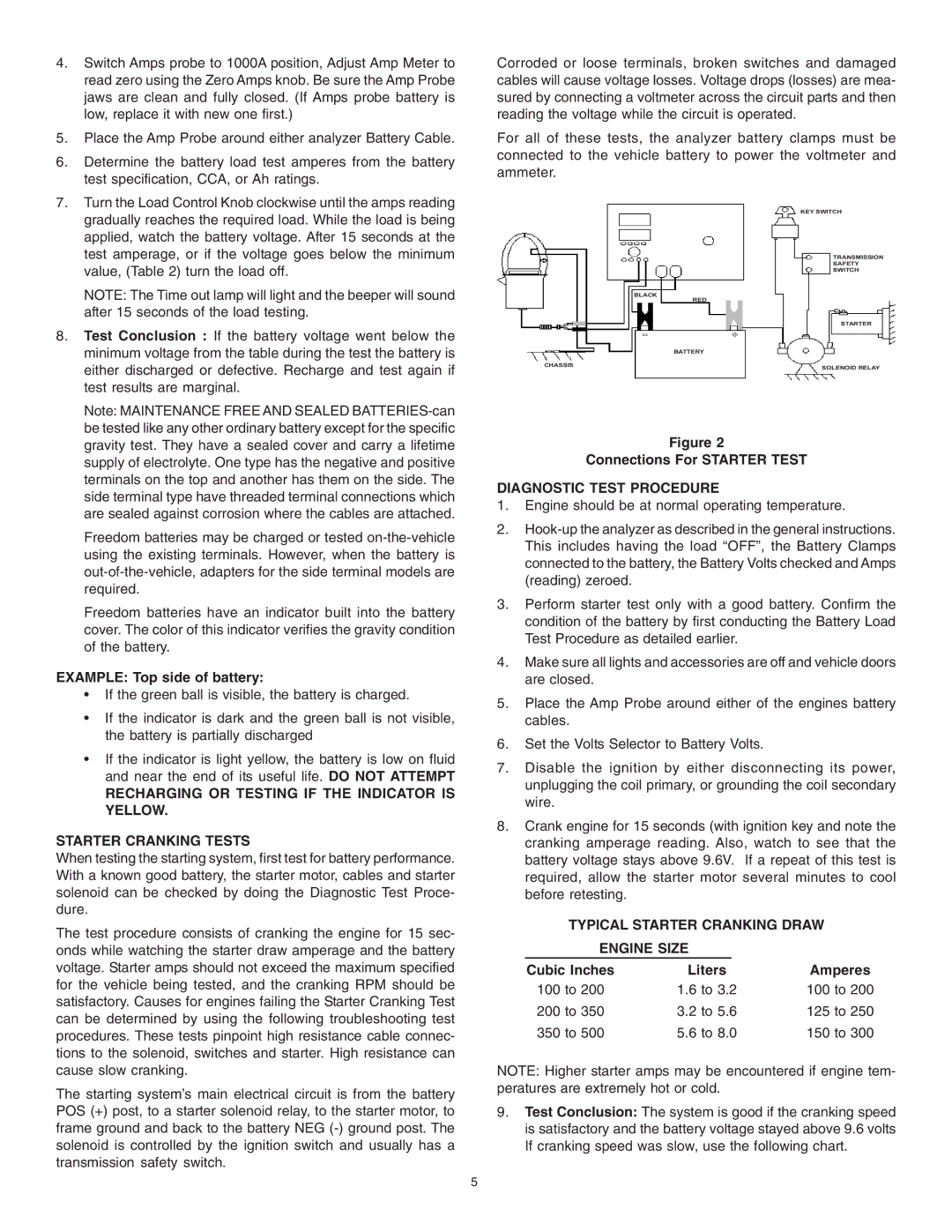
The starting system’s main electrical circuit is from the battery POS (+) post, to a starter solenoid relay, to the starter motor, to frame ground and back to the battery NEG
Corroded or loose terminals, broken switches and damaged cables will cause voltage losses. Voltage drops (losses) are mea- sured by connecting a voltmeter across the circuit parts and then reading the voltage while the circuit is operated.
For all of these tests, the analyzer battery clamps must be connected to the vehicle battery to power the voltmeter and ammeter.
KEY SWITCH
TRANSMISSION
SAFETY
SWITCH
BLACK
RED
STARTER
-+
| BATTERY |
CHASSIS | SOLENOID RELAY |
|
Figure 2
Connections For STARTER TEST
DIAGNOSTIC TEST PROCEDURE
1.Engine should be at normal operating temperature.
2.
3.Perform starter test only with a good battery. Confirm the condition of the battery by first conducting the Battery Load Test Procedure as detailed earlier.
4.Make sure all lights and accessories are off and vehicle doors are closed.
5.Place the Amp Probe around either of the engines battery cables.
6.Set the Volts Selector to Battery Volts.
7.Disable the ignition by either disconnecting its power, unplugging the coil primary, or grounding the coil secondary wire.
8.Crank engine for 15 seconds (with ignition key and note the cranking amperage reading. Also, watch to see that the battery voltage stays above 9.6V. If a repeat of this test is required, allow the starter motor several minutes to cool before retesting.
TYPICAL STARTER CRANKING DRAW
ENGINE SIZE |
|
| |
Cubic Inches | Liters | Amperes | |
100 to 200 | 1.6 to 3.2 | 100 to 200 | |
200 to 350 | 3.2 to 5.6 | 125 to 250 | |
350 to 500 | 5.6 to 8.0 | 150 to 300 | |
NOTE: Higher starter amps may be encountered if engine tem- peratures are extremely hot or cold.
9.Test Conclusion: The system is good if the cranking speed is satisfactory and the battery voltage stayed above 9.6 volts If cranking speed was slow, use the following chart.
5
