NUDE TC SHOCK AND TRAC-LOC
REMOTE CONTROL LEVER
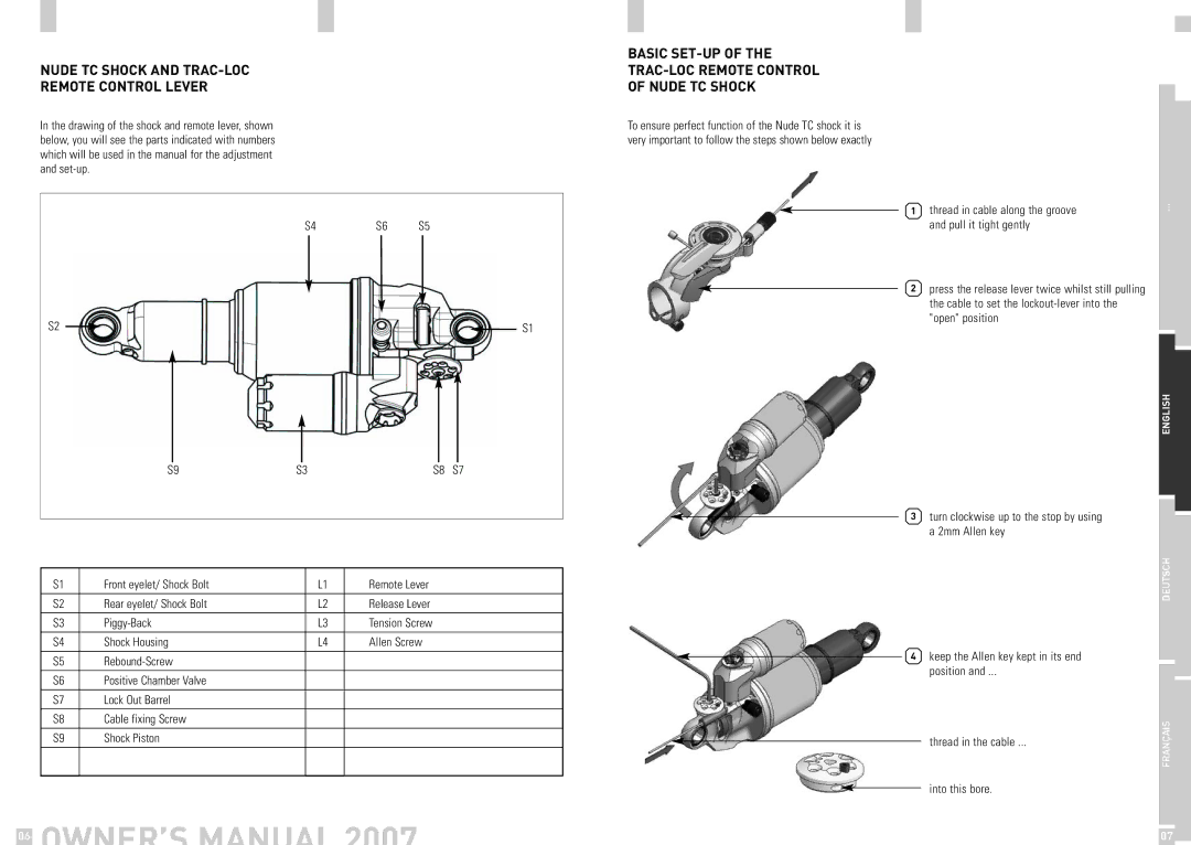
In the drawing of the shock and remote lever, shown below, you will see the parts indicated with numbers which will be used in the manual for the adjustment and
S4 | S6 | S5 |
S2 |
|
|
| S1 |
|
| |||
|
S9 | S3 | S8 | S7 |
S1 | Front eyelet/ Shock Bolt | L1 | Remote Lever |
|
|
|
|
S2 | Rear eyelet/ Shock Bolt | L2 | Release Lever |
|
|
|
|
S3 | L3 | Tension Screw | |
|
|
|
|
S4 | Shock Housing | L4 | Allen Screw |
|
|
|
|
S5 |
|
| |
|
|
|
|
S6 | Positive Chamber Valve |
|
|
|
|
|
|
S7 | Lock Out Barrel |
|
|
|
|
|
|
S8 | Cable fixing Screw |
|
|
|
|
|
|
S9 | Shock Piston |
|
|
|
|
|
|
|
|
|
|
BASIC SET-UP OF THE
TRAC-LOC REMOTE CONTROL
OF NUDE TC SHOCK
To ensure perfect function of the Nude TC shock it is very important to follow the steps shown below exactly
|
|
|
|
|
|
| thread in cable along the groove | … |
|
1 |
|
| |||||||
|
|
|
|
|
|
| and pull it tight gently |
|
|
|
|
| 2 | press the release lever twice whilst still pulling |
|
| |||
|
|
| |||||||
|
|
|
|
|
|
| the cable to set the |
|
|
|
|
|
|
|
|
| "open" position |
|
|
|
|
|
|
|
|
|
|
|
|
|
|
|
|
|
|
|
| ENGLISH |
|
|
|
|
|
|
|
|
|
| |
|
|
|
|
| 3 | turn clockwise up to the stop by using |
|
| |
|
|
|
|
|
|
| |||
|
|
|
| ||||||
|
| ||||||||
|
|
|
| ||||||
|
|
|
|
|
|
| a 2mm Allen key |
|
|
|
|
|
|
|
|
|
| DEUTSCH |
|
|
| 4 | keep the Allen key kept in its end |
|
| ||||
|
|
| |||||||
|
|
|
|
|
|
| position and ... |
|
|
|
|
|
|
|
|
| thread in the cable ... | FRANÇAIS |
|
|
|
|
|
|
|
|
| ||
|
|
|
|
|
|
|
|
| |
into this bore.
| OWNER’S MANUAL 2007 |
|
06 | 07 |