34 ST11950 and ST12550 Installation Guide, Rev. D
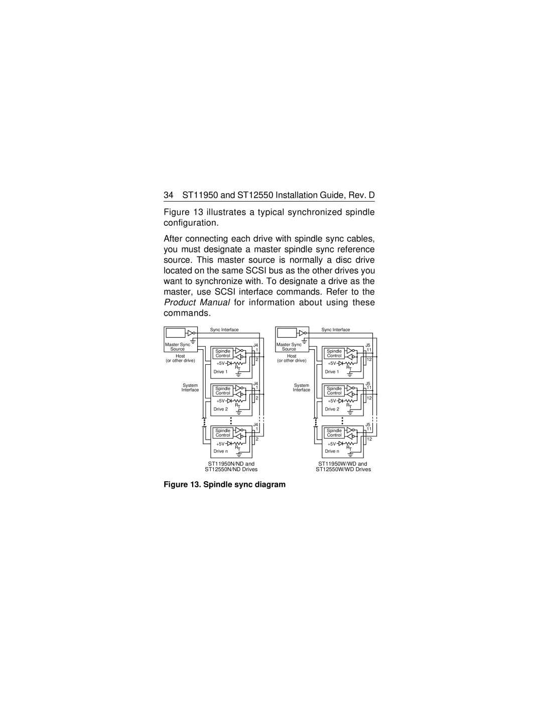
Figure 13 illustrates a typical synchronized spindle configuration.
After connecting each drive with spindle sync cables, you must designate a master spindle sync reference source. This master source is normally a disc drive located on the same SCSI bus as the other drives you want to synchronize with. To designate a drive as the master, use SCSI interface commands. Refer to the Product Manual for information about using these commands.
| Sync Interface |
| |
Master Sync |
| J4 | |
Source | Spindle | 1 | |
Host | Control | 2 | |
(or other drive) | +5V | ||
|
| ||
| RT |
| |
| Drive 1 |
| |
System |
| J4 | |
Spindle | 1 | ||
Interface | |||
| Control |
| |
| +5V | 2 | |
|
| ||
| RT |
| |
| Drive 2 |
| |
|
| J4 | |
| Spindle | 1 | |
| Control | 2 | |
| +5V | ||
|
| ||
| RT |
| |
| Drive n |
|
ST11950N/ND and
ST12550N/ND Drives
| Sync Interface |
| |
Master Sync |
| J5 | |
Source | Spindle | 11 | |
Host | Control | 12 | |
(or other drive) | +5V | ||
|
| ||
| RT |
| |
| Drive 1 |
| |
System |
| J5 | |
Spindle | 11 | ||
Interface | |||
| Control |
| |
| +5V | 12 | |
|
| ||
| RT |
| |
| Drive 2 |
| |
|
| J5 | |
| Spindle | 11 | |
| Control | 12 | |
| +5V | ||
|
| ||
| RT |
| |
| Drive n |
|
ST11950W/WD and
ST12550W/WD Drives
