4.0Interface description
The drives use the
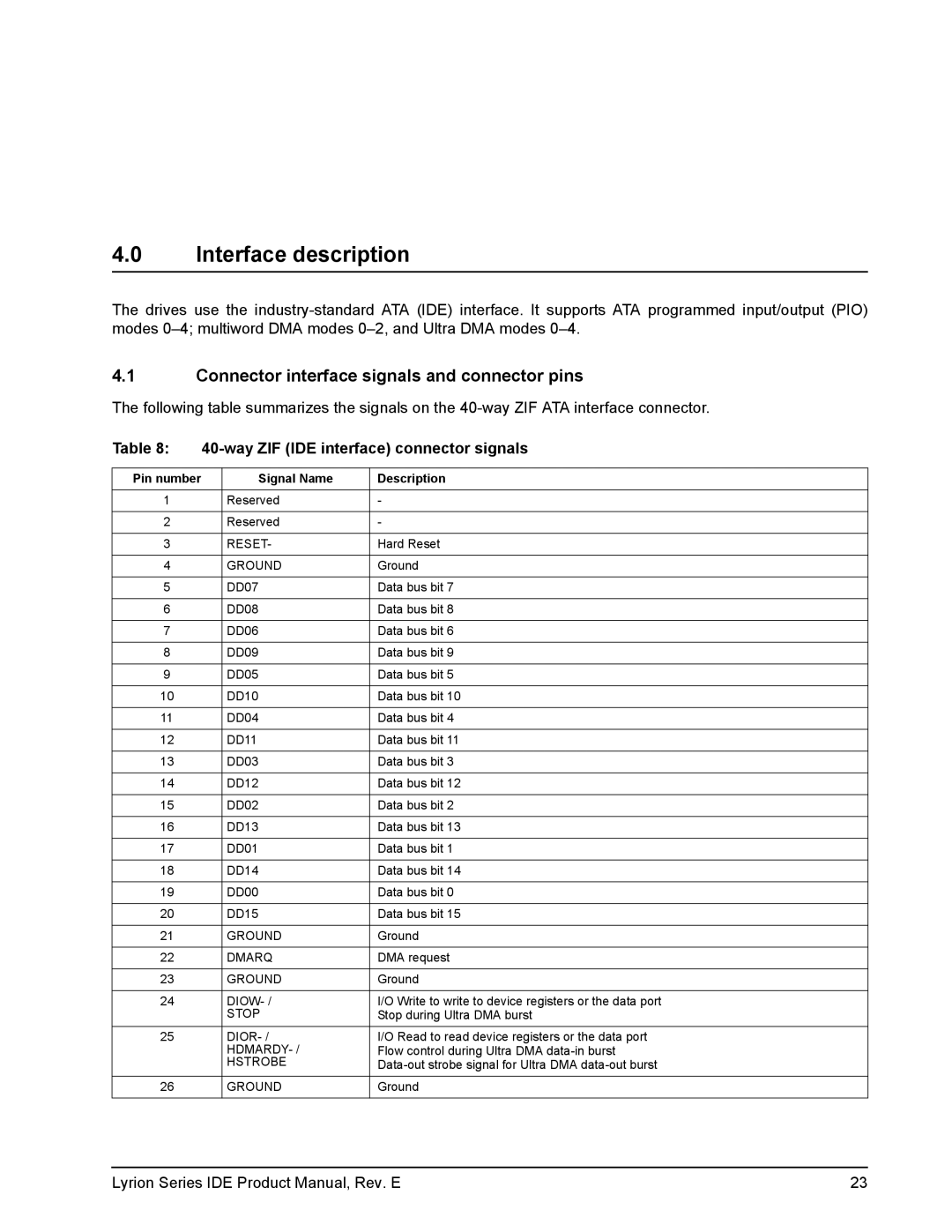
4.1Connector interface signals and connector pins
The following table summarizes the signals on the
Table 8: |
| ||
|
|
|
|
Pin number |
| Signal Name | Description |
|
|
|
|
1 |
| Reserved | - |
|
|
|
|
2 |
| Reserved | - |
|
|
|
|
3 |
| RESET- | Hard Reset |
|
|
|
|
4 |
| GROUND | Ground |
|
|
|
|
5 |
| DD07 | Data bus bit 7 |
|
|
|
|
6 |
| DD08 | Data bus bit 8 |
|
|
|
|
7 |
| DD06 | Data bus bit 6 |
|
|
|
|
8 |
| DD09 | Data bus bit 9 |
|
|
|
|
9 |
| DD05 | Data bus bit 5 |
|
|
|
|
10 |
| DD10 | Data bus bit 10 |
|
|
|
|
11 |
| DD04 | Data bus bit 4 |
|
|
|
|
12 |
| DD11 | Data bus bit 11 |
|
|
|
|
13 |
| DD03 | Data bus bit 3 |
|
|
|
|
14 |
| DD12 | Data bus bit 12 |
|
|
|
|
15 |
| DD02 | Data bus bit 2 |
|
|
|
|
16 |
| DD13 | Data bus bit 13 |
|
|
|
|
17 |
| DD01 | Data bus bit 1 |
|
|
|
|
18 |
| DD14 | Data bus bit 14 |
|
|
|
|
19 |
| DD00 | Data bus bit 0 |
|
|
|
|
20 |
| DD15 | Data bus bit 15 |
|
|
|
|
21 |
| GROUND | Ground |
|
|
|
|
22 |
| DMARQ | DMA request |
|
|
|
|
23 |
| GROUND | Ground |
|
|
|
|
24 |
| I/O Write to write to device registers or the data port | |
|
| STOP | Stop during Ultra DMA burst |
|
|
|
|
25 |
| I/O Read to read device registers or the data port | |
|
| Flow control during Ultra DMA | |
|
| HSTROBE | |
|
|
|
|
26 |
| GROUND | Ground |
|
|
|
|
Lyrion Series IDE Product Manual, Rev. E | 23 |