|
| ENFORCER | ||||
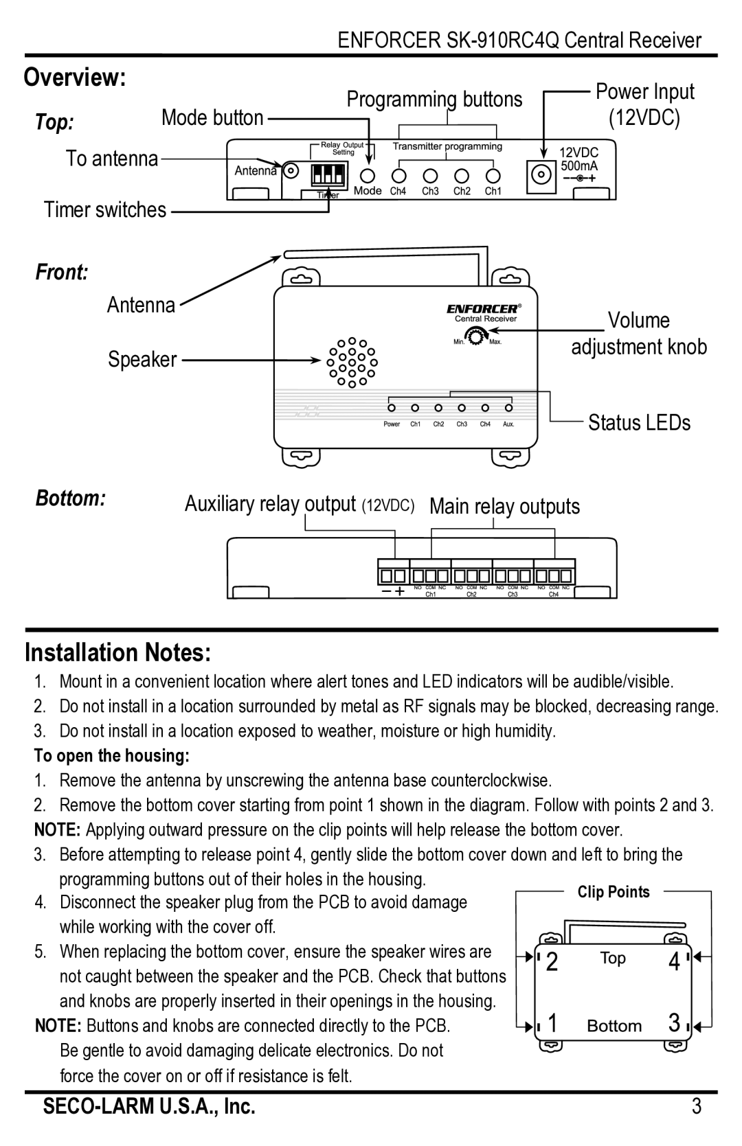
Overview: |
| Programming buttons | Power Input | |||
|
| |||||
Top: | Mode button | (12VDC) | ||||
|
|
| ||||
|
|
| ||||
|
|
|
|
|
| |
To antenna |
Timer switches |
Front:
| Antenna | Volume |
|
| |
| Speaker | adjustment knob |
|
| |
|
| Status LEDs |
Bottom: |
| Auxiliary relay output (12VDC) Main relay outputs |
Installation Notes:
1. Mount in a convenient location where alert tones and LED indicators will be audible/visible.
2.Do not install in a location surrounded by metal as RF signals may be blocked, decreasing range.
3.Do not install in a location exposed to weather, moisture or high humidity.
To open the housing:
1.Remove the antenna by unscrewing the antenna base counterclockwise.
2.Remove the bottom cover starting from point 1 shown in the diagram. Follow with points 2 and 3. NOTE: Applying outward pressure on the clip points will help release the bottom cover.
3.Before attempting to release point 4, gently slide the bottom cover down and left to bring the
programming buttons out of their holes in the housing.
4. Disconnect the speaker plug from the PCB to avoid damage while working with the cover off.
5. When replacing the bottom cover, ensure the speaker wires are not caught between the speaker and the PCB. Check that buttons and knobs are properly inserted in their openings in the housing.
NOTE: Buttons and knobs are connected directly to the PCB. Be gentle to avoid damaging delicate electronics. Do not force the cover on or off if resistance is felt.
3 |
