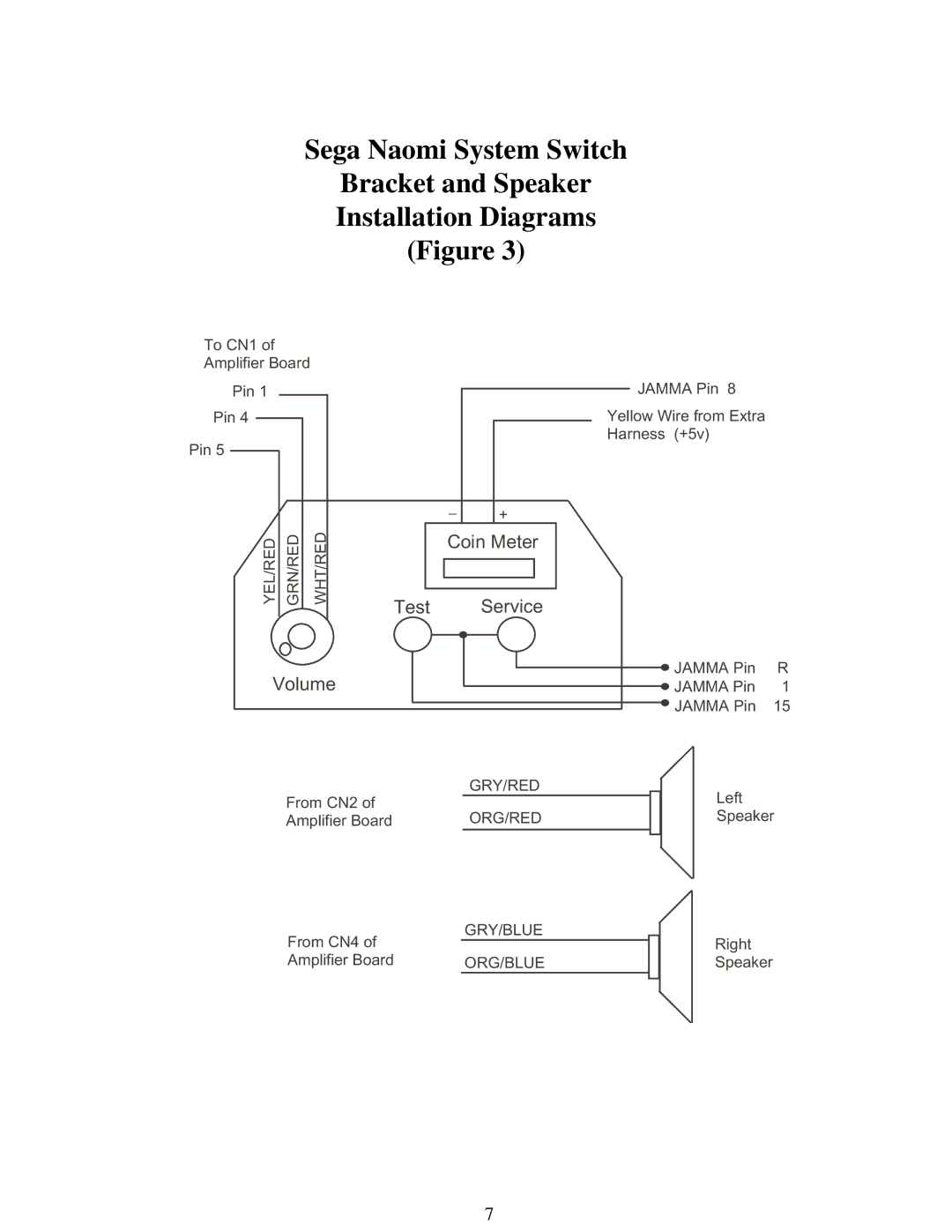
Sega Naomi System Switch
Bracket and Speaker
Installation Diagrams
(Figure 3)
To CN1 of
Amplifier Board
Pin 1
Pin 4
Pin 5
YEL/RED | GRN/RED |
WHT/RED
Test
JAMMA Pin 8
Yellow Wire from Extra
Harness (+5v)
_ | + |
|
Coin Meter
Service
Volume
From CN2 of Amplifier Board
JAMMA Pin | R |
JAMMA Pin | 1 |
JAMMA Pin | 15 |
GRY/RED |
| Left |
|
| |
ORG/RED |
| Speaker |
|
|
|
From CN4 of | GRY/BLUE |
|
| Right |
|
| |||
|
|
| ||
Amplifier Board | ORG/BLUE |
|
| Speaker |
|
|
|
|
|
7