DIP Switch Tables
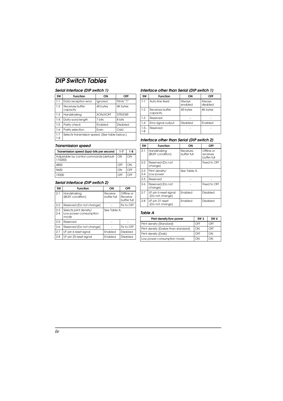
Serial Interface (DIP switch 1)
SW | Function | ON | OFF |
|
|
|
|
Data reception error | Ignored | Prints “?” | |
|
|
|
|
Receives buffer | 45 bytes | 4K bytes | |
| capacity |
|
|
|
|
|
|
Handshaking | XON/XOFF | DTR/DSR | |
|
|
|
|
Data word length | 7 bits | 8 bits | |
|
|
|
|
Parity check | Enabled | Disabled | |
|
|
|
|
Parity selection | Even | Odd | |
|
|
|
|
Selects transmission speed. (See table below.) | |||
|
|
| |
|
|
|
|
Transmission speed
Transmission speed | ||
|
|
|
Adjustable by control commands (default: | ON | ON |
115200) |
|
|
|
|
|
4800 | OFF | ON |
|
|
|
9600 | ON | OFF |
|
|
|
19200 | OFF | OFF |
|
|
|
Serial Interface (DIP switch 2)
SW | Function | ON | OFF |
|
|
|
|
Handshaking | Receive | Offline or | |
| (BUSY condition) | buffer full | Receive |
|
|
| buffer full |
|
|
|
|
Reserved (Do not change) | – | Fix to OFF | |
|
|
|
|
Selects print density/ | See Table A. | ||
Low power comsumption |
|
| |
| mode |
|
|
|
|
|
|
Reserved | – | – | |
|
|
|
|
Reserved (Do not change) | – | Fix to OFF | |
|
|
|
|
I/F pin 6 reset signal | Enabled | Disabled | |
|
|
|
|
I/F pin 25 reset signal | Enabled | Disabled | |
|
|
|
|
Interface other than Serial (DIP switch 1)
SW | Function | ON | OFF |
|
|
|
|
Auto line feed | Always | Always | |
|
| enabled | disabled |
|
|
|
|
Receives buffer | 45 bytes | 4K bytes | |
| capacity |
|
|
|
|
|
|
Reserved | – | – | |
|
|
|
|
Error signal output | Disabled | Enabled | |
|
|
|
|
Reserved | – | – | |
|
|
| |
|
|
|
|
Interface other than Serial (DIP switch 2)
SW | Function | ON | OFF |
|
|
|
|
Handshaking | Receives | Offline or | |
| (BUSY condition) | buffer full | receives |
|
|
| buffer full |
|
|
|
|
Reserved (Do not | – | Fixed to OFF | |
| change) |
|
|
|
|
|
|
Print density/ | See Table A. |
| |
Low power |
|
| |
|
|
|
|
Reserved | – | – | |
|
|
|
|
Reserved (Do not | – | Fixed to OFF | |
| change) |
|
|
|
|
|
|
I/F pin 6 reset signal | Enabled | Disabled | |
| (Do not change) |
|
|
|
|
|
|
I/F pin 31 reset | Enabled | Disabled | |
| (Do not change) |
|
|
|
|
|
|
Table A
Print density/low power | SW 3 | SW 4 |
|
|
|
Print density (Standard) | OFF | OFF |
|
|
|
Print density (Darker than standard) | ON | OFF |
|
|
|
Print density (Dark) | OFF | ON |
|
|
|
Low power consumption mode | ON | ON |
|
|
|
iv