Installation Procedure (Rack Setup)
1.Remove the four flathead screws from the left and right sides of the switch device's console panel.
2.Remove the console panel from the switch device, and attach the rack mount bracket (small) to it. (Use the screws that were removed in step 1.)
3.Attach the rack mount bracket (large) to the rear panel side of the switch device with the flathead screws provided (six).
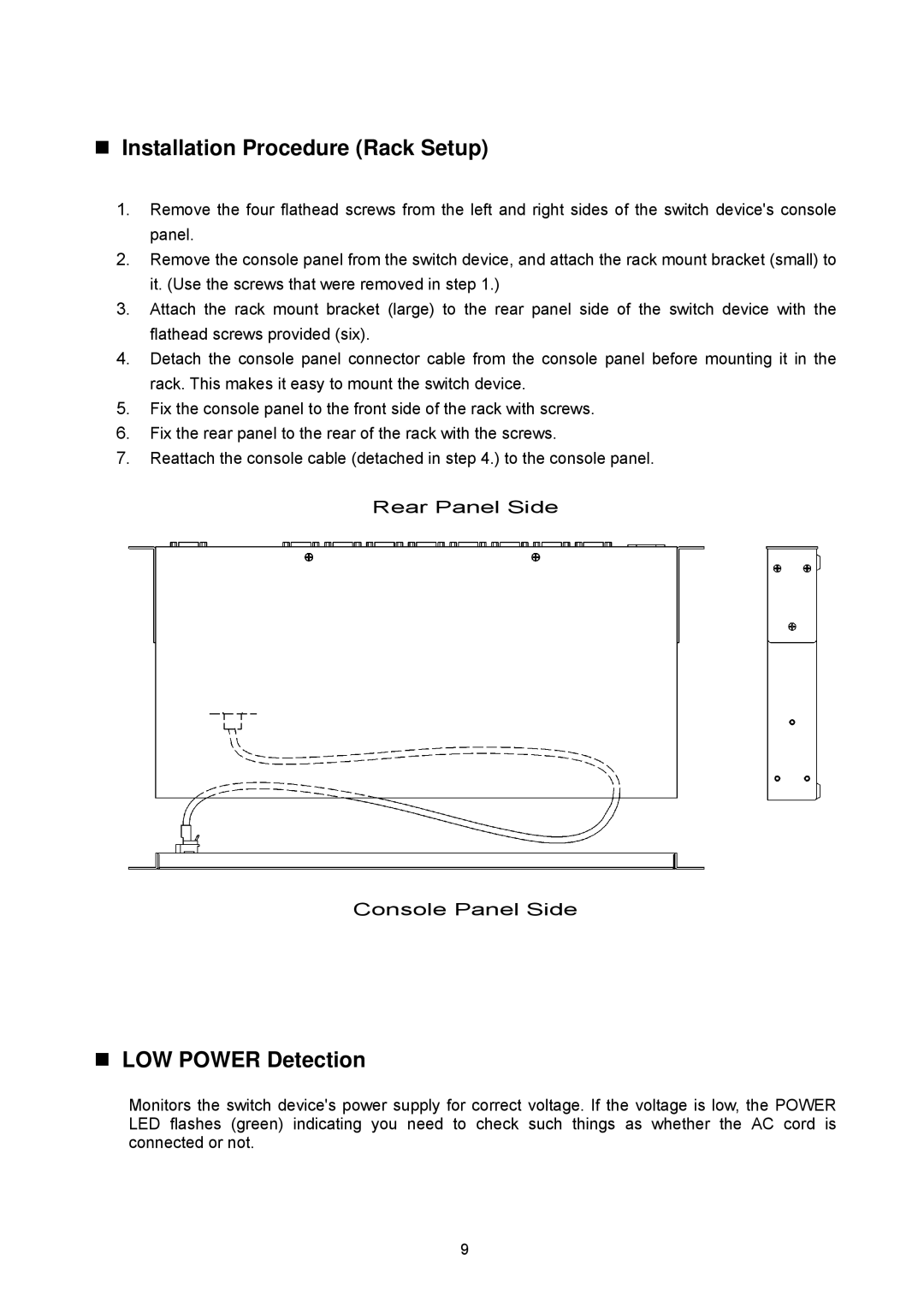
4.Detach the console panel connector cable from the console panel before mounting it in the rack. This makes it easy to mount the switch device.
5.Fix the console panel to the front side of the rack with screws.
6.Fix the rear panel to the rear of the rack with the screws.
7.Reattach the console cable (detached in step 4.) to the console panel.
Rear Panel Side
Console Panel Side
LOW POWER Detection
Monitors the switch device's power supply for correct voltage. If the voltage is low, the POWER LED flashes (green) indicating you need to check such things as whether the AC cord is connected or not.
9