Part names
TV (Front)
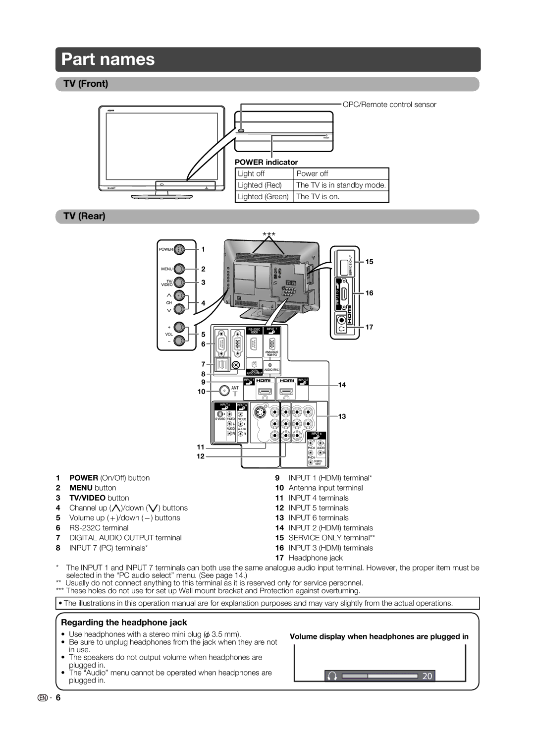
OPC/Remote control sensor
POWER indicator
Light off | Power off |
|
|
Lighted (Red) | The TV is in standby mode. |
|
|
Lighted (Green) | The TV is on. |
|
|
TV (Rear)
|
| *** |
|
|
| 1 |
|
|
| 2 | 15 |
|
|
| |
|
| 3 |
|
|
|
| 16 |
|
| 4 |
|
|
| 5 | 17 |
|
|
| |
|
| 6 |
|
|
| 7 |
|
|
| 8 |
|
|
| 9 | 14 |
|
| 10 | |
|
|
| |
|
|
| 13 |
|
| 11 |
|
|
| 12 |
|
1 | POWER (On/Off) button | 9 INPUT 1 (HDMI) terminal* | |
2 | MENU button | 10 Antenna input terminal | |
3 | TV/VIDEO button | 11 | INPUT 4 terminals |
4 | Channel up (r)/down (s) buttons | 12 | INPUT 5 terminals |
5 | Volume up (e)/down (f) buttons | 13 | INPUT 6 terminals |
6 | 14 INPUT 2 (HDMI) terminals | ||
7 | DIGITAL AUDIO OUTPUT terminal | 15 | SERVICE ONLY terminal** |
8 | INPUT 7 (PC) terminals* | 16 | INPUT 3 (HDMI) terminals |
17 Headphone jack
*The INPUT 1 and INPUT 7 terminals can both use the same analogue audio input terminal. However, the proper item must be selected in the “PC audio select” menu. (See page 14.)
**Usually do not connect anything to this terminal as it is reserved only for service personnel.
***These holes do not use for set up Wall mount bracket and Protection against overturning.
•The illustrations in this operation manual are for explanation purposes and may vary slightly from the actual operations.
Regarding the headphone jack
•Use headphones with a stereo mini plug (![]() 3.5 mm).
3.5 mm).
•Be sure to unplug headphones from the jack when they are not in use.
•The speakers do not output volume when headphones are plugged in.
•The “Audio” menu cannot be operated when headphones are plugged in.
Volume display when headphones are plugged in
20
![]()
![]() 6
6