Preparation
Antenna connection
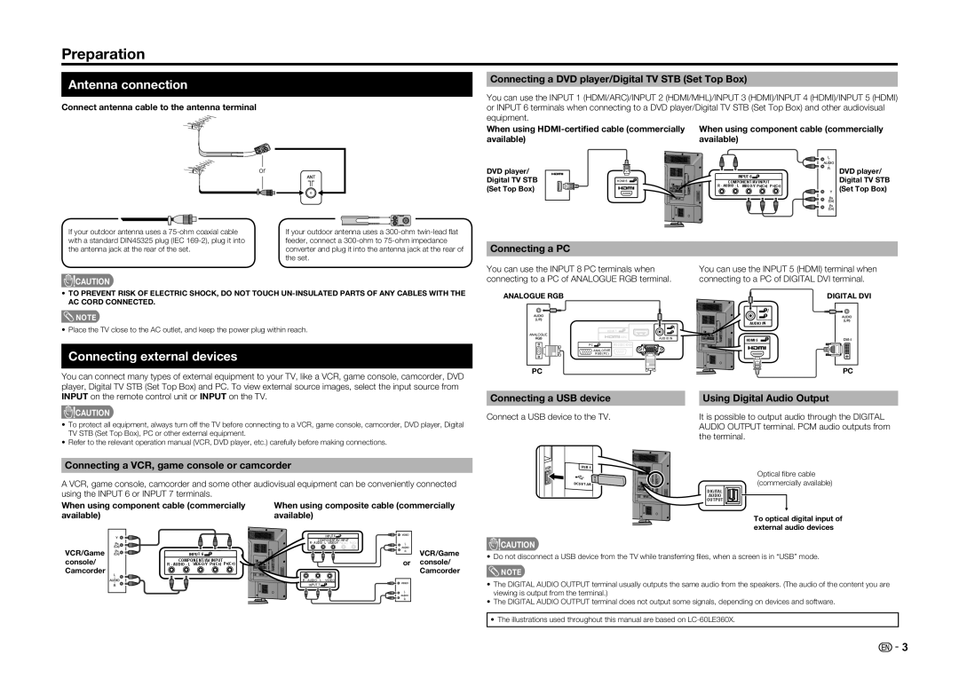
Connect antenna cable to the antenna terminal
Connecting a DVD player/Digital TV STB (Set Top Box)
You can use the INPUT 1 (HDMI/ARC)/INPUT 2 (HDMI/MHL)/INPUT 3 (HDMI)/INPUT 4 (HDMI)/INPUT 5 (HDMI) or INPUT 6 terminals when connecting to a DVD player/Digital TV STB (Set Top Box) and other audiovisual equipment.
When using | When using component cable (commercially |
available) | available) |
or | DVD player/ |
| Digital TV STB |
| (Set Top Box) |
HDMI 5
5
INPUT 6 | 6 |
|
|
|
|
| ||
COMPONENT/AV INPUT | PR(CR) | |||||||
R - AUDIO - L VIDEO/Y PB(CB) | ||||||||
|
|
|
|
|
|
|
|
|
DVD player/ Digital TV STB (Set Top Box)
If your outdoor antenna uses a | If your outdoor antenna uses a |
with a standard DIN45325 plug (IEC | feeder, connect a |
the antenna jack at the rear of the set. | converter and plug it into the antenna jack at the rear of |
| the set. |
![]() CAUTION
CAUTION
•TO PREVENT RISK OF ELECTRIC SHOCK, DO NOT TOUCH
![]() NOTE
NOTE
• Place the TV close to the AC outlet, and keep the power plug within reach.
Connecting external devices
You can connect many types of external equipment to your TV, like a VCR, game console, camcorder, DVD player, Digital TV STB (Set Top Box) and PC. To view external source images, select the input source from
Connecting a PC
You can use the INPUT 8 PC terminals when connecting to a PC of ANALOGUE RGB terminal.
ANALOGUE RGB
|
| 1 | 5 |
| HDMI 1 | 8 | |
ANALOGUE |
| ||
| ARC | AUDIO IN | |
|
| ||
|
|
| |
PC |
| ||
| ANALOGUE |
|
|
| RGB (PC) |
|
|
PC
You can use the INPUT 5 (HDMI) terminal when connecting to a PC of DIGITAL DVI terminal.
DIGITAL DVI
| 5 |
| 8 |
AUDIO IN | |
HDMI 5 | 5 |
| |
PC
INPUT on the remote control unit or INPUT on the TV.
![]() CAUTION
CAUTION
•To protect all equipment, always turn off the TV before connecting to a VCR, game console, camcorder, DVD player, Digital TV STB (Set Top Box), PC or other external equipment.
•Refer to the relevant operation manual (VCR, DVD player, etc.) carefully before making connections.
Connecting a VCR, game console or camcorder
A VCR, game console, camcorder and some other audiovisual equipment can be conveniently connected using the INPUT 6 or INPUT 7 terminals.
When using component cable (commercially | When using composite cable (commercially | |
available) | available) |
|
| INPUT 6 | 6 |
Connecting a USB device
Connect a USB device to the TV.
USB 1
DC5V 1.5A![]()
Using Digital Audio Output
It is possible to output audio through the DIGITAL AUDIO OUTPUT terminal. PCM audio outputs from the terminal.
Optical fi bre cable (commercially available)
DIGITAL
AUDIO
OUTPUT
To optical digital input of external audio devices
|
|
| COMPONENT/AV INPUT | PR(CR) | |
|
|
| R - AUDIO - L VIDEO/Y PB(CB) | ||
VCR/Game | INPUT 6 | 6 |
|
| VCR/Game |
|
|
| |||
console/ | COMPONENT/AV INPUT | PR(CR) |
| or console/ | |
R - AUDIO - L VIDEO/Y PB(CB) |
| ||||
Camcorder |
|
|
|
| Camcorder |
|
|
| R - AUDIO - L | VIDEO |
|
|
|
| INPUT 7 | 7 |
|
![]() CAUTION
CAUTION
• Do not disconnect a USB device from the TV while transferring fi les, when a screen is in “USB” mode.
![]() NOTE
NOTE
•The DIGITAL AUDIO OUTPUT terminal usually outputs the same audio from the speakers. (The audio of the content you are viewing is output from the terminal.)
•The DIGITAL AUDIO OUTPUT terminal does not output some signals, depending on devices and software.
•The illustrations used throughout this manual are based on
![]() - 3
- 3