HIGH VOLTAGE RECTIFIER ASSEMBLY AND HIGH VOLTAGE CAPACITOR REMOVAL
To remove the components, proceed as follows.
1.Disconnect the power supply cord and then remove outer case.
2.Open the door and block it open.
3.Discharge high voltage capacitor.
4.Disconnect H.V. wire of the high voltage rectifier assembly from the magnetron and the power transformer.
5.Disconnect the filament lead of the power transformer from the high voltage capacitor.
6.Remove one (1) screw holding earth side terminal of the high voltage rectifier assembly.
7.Disconnect all the leads and terminals of high voltage rectifier assembly from the high voltage capacitor.
8.Now, the high voltage rectifier assembly should be free.
9.Remove one (1) screw holding the capacitor holder to the oven cavity rear plate.
10.Remove one (1) screw holding the fan duct to the oven cavity rear plate.
11.Release the capacitor holder from the fan duct.
12.Remove the capacitor from the capacitor holder.
13.Now, the capacitor should be free.
CAUTION: WHEN REPLACING HIGH VOLTAGE RECTI- FIER AND HIGH VOLTAGE CAPACITOR, GROUND SIDE TERMINAL OF THE HIGH VOLT- AGE RECTIFIER MUST BE SECURED FIRMLY WITH A GROUNDING SCREW.
MAGNETRON REMOVAL
1.Disconnect the power supply cord and then remove outer case.
2.Open the door and block it open.
3.Discharge high voltage capacitor.
4.Disconnect the high voltage wire of the high voltage rectifier assembly and filament lead of the transformer from the magnetron.
5.Remove the one (1) screw holding the airguide to the magnetron and remove the airguide.
6.Remove the one (1) screw holding the insertion plate A to the magnetron and remove the insertion plate A.
7.Remove the one (1) screw holding the chassis support to the magnetron.
8.Release the tabs of air intake duct from the chassis support and the oven cavity.
9.Move the air intake duct to the left.
10.Carefully remove four (4) screws holding magnetron to waveguide, when removing the screws hold the magnetron to prevent it from falling.
11.Remove the magnetron from the waveguide with care so the magnetron antenna is not hit by any metal object around the antenna.
CAUTION: WHEN REPLACING THE MAGNETRON, BE SURE THE R.F. GASKET IS IN PLACE AND THE MAGNETRON MOUNTING SCREWS ARE TIGHTENED SECURELY.
CONTROL PANEL ASSEMBLY REMOVAL
CONTROL PANEL ASSEMBLY
1.Disconnect the power supply cord and then remove outer case.
2.Open the door and block it open.
3.Discharge high voltage capacitor.
4.Disconnect the main wire harness from the control unit.
5.Remove the one (1) screw holding the control panel assembly to the oven cavity front plate.
6.Lift up the control panel assembly.
7.Now, the control panel assembly is free.
CONTROL UNIT
8.Remove the five (5) screws holding the control unit to the control panel frame.
9.Remove the control unit from the control panel frame.
10.Now, the control unit is free.
TIMER KNOB
11.After removing the control unit, release the tab of the timer knob from the hole of the control panel.
12. Now, the timer knob is free.
NOTE: 1. Before attaching a new timer sheet, wipe off remaining adhesive on the control panel frame surfaces completely with a soft cloth soaked in alcohol.
2.When attaching the timer sheet to the control panel frame, adjust the upper edge and right edge of the timer sheet to the correct position of control panel frame.
3.Stick the timer sheet firmly to the control panel frame by rubbing with a soft cloth so not to cause scratches.
OVEN LAMP AND LAMP SOCKET REMOVAL
1.Disconnect the power supply cord and then remove outer case.
2.Open the door and block it open.
3.Discharge high voltage capacitor.
4.Lift up the oven lamp socket from air intake duct.
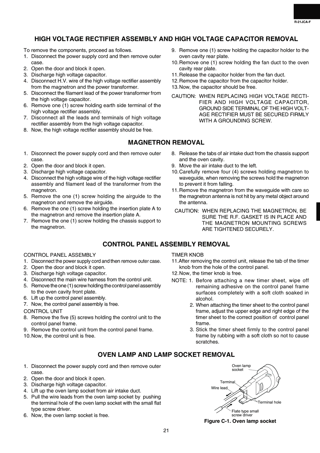
5.Pull the wire leads from the oven lamp socket by pushing the terminal hole of the oven lamp socket with the small flat type screw driver.
6.Now, the oven lamp socket is free.
Oven lamp socket ![]()
Terminal
Wire lead
![]() Terminal hole
Terminal hole
Flate type small screw driver
Figure C-1. Oven lamp socket
21