TEST PROCEDURES
PROCEDURE
LETTER
COMPONENT TEST
HBLOWN MONITOR FUSE TEST
1.Disconnect the power supply cord, and then remove outer case.
2.Open the door and block it open.
3.Discharge high voltage capacitor.
4.If the monitor fuse is blown when the door is opened, check the primary interlock relay, secondary interlock switch and monitor switch according to the "TEST PROCEDURE" for those switches before replacing the blown monitor fuse.
CAUTION: BEFORE REPLACING A BLOWN MONITOR FUSE, TEST THE PRIMARY INTERLOCK RELAY, SECONDARY INTERLOCK SWITCH, DOOR SENSING SWITCH AND MONITOR SWITCH FOR PROPER OPERATION.
If the monitor fuse is blown by improper switch operation, the monitor fuse and monitor switch must be replaced with "monitor fuse and monitor switch assembly" part number
5.Reconnect all leads removed from components during testing.
6.Reinstall the outer case (cabinet).
7.Reconnect the power supply cord after the outer case is installed.
8.Run the oven and check all functions.
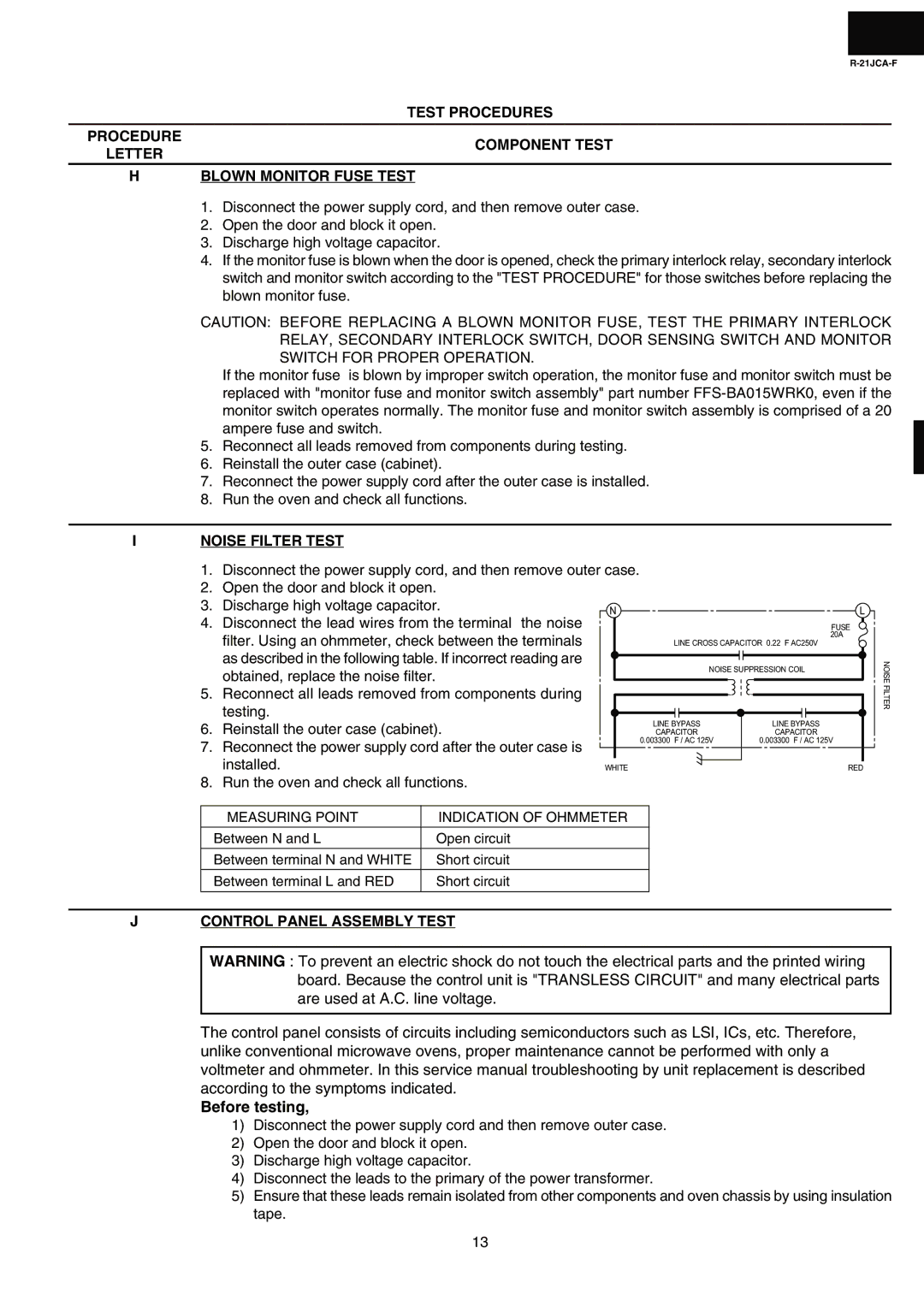
INOISE FILTER TEST
1.Disconnect the power supply cord, and then remove outer case.
2.Open the door and block it open.
3. | Discharge high voltage capacitor. | N |
|
|
|
| L | |||||||||
4. | Disconnect the lead wires from the terminal the noise |
|
|
|
| |||||||||||
|
|
|
|
|
|
|
|
|
|
|
|
|
| FUSE | ||
| filter. Using an ohmmeter, check between the terminals |
|
|
|
|
|
|
|
|
|
|
|
|
|
| 20A |
|
| LINE CROSS CAPACITOR 0.22 F AC250V | ||||||||||||||
| as described in the following table. If incorrect reading are |
|
|
|
|
|
|
|
|
|
|
|
|
|
|
|
|
|
|
|
|
| NOISE SUPPRESSION COIL | ||||||||||
| obtained, replace the noise filter. |
|
|
|
|
| ||||||||||
|
|
|
|
|
|
|
|
|
|
|
|
|
|
|
| |
5. | Reconnect all leads removed from components during |
|
|
|
|
|
|
|
|
|
|
|
|
|
|
|
|
|
|
|
|
|
|
|
|
|
|
|
|
|
| ||
| testing. |
|
|
|
|
|
|
|
|
|
|
|
|
|
|
|
6. | Reinstall the outer case (cabinet). |
| LINE BYPASS | LINE BYPASS | ||||||||||||
| CAPACITOR | CAPACITOR | ||||||||||||||
7. | Reconnect the power supply cord after the outer case is |
| 0.003300 F / AC 125V | 0.003300 F / AC 125V | ||||||||||||
|
|
|
|
|
|
|
|
|
|
|
|
|
|
| ||
| installed. |
|
|
|
|
|
|
|
|
|
|
|
|
|
|
|
| WHITE |
|
|
|
| RED | ||||||||||
8. | Run the oven and check all functions. |
|
|
|
|
|
|
|
|
|
|
|
|
|
|
|
NOISE FILTER
MEASURING POINT | INDICATION OF OHMMETER |
|
|
Between N and L | Open circuit |
|
|
Between terminal N and WHITE | Short circuit |
|
|
Between terminal L and RED | Short circuit |
|
|
JCONTROL PANEL ASSEMBLY TEST
WARNING : To prevent an electric shock do not touch the electrical parts and the printed wiring board. Because the control unit is "TRANSLESS CIRCUIT" and many electrical parts are used at A.C. line voltage.
The control panel consists of circuits including semiconductors such as LSI, ICs, etc. Therefore, unlike conventional microwave ovens, proper maintenance cannot be performed with only a voltmeter and ohmmeter. In this service manual troubleshooting by unit replacement is described according to the symptoms indicated.
Before testing,
1)Disconnect the power supply cord and then remove outer case.
2)Open the door and block it open.
3)Discharge high voltage capacitor.
4)Disconnect the leads to the primary of the power transformer.
5)Ensure that these leads remain isolated from other components and oven chassis by using insulation tape.
13