POWER SUPPLY CORD REPLACEMENT
Removal
1.Disconnect the power supply cord and then remove outer case.
2.Open the door and block it open.
3.Discharge high voltage capacitor.
4.Remove the one (1) screw holding the green wire to the cavity rear plate.
5.Disconnect the wire leads of the power supply cord from the noisew filter.
6.Release the power supply cord from the oven cavity rear plate.
Oven Cavity |
| Power Supply Cord | |
Rear Plate |
| ||
|
|
| |
Screw |
|
|
|
Green |
|
|
|
Wire |
|
| Chassis |
|
|
| |
Black Wire |
| RED | Support |
| L | WHT |
|
White Wire | N |
|
|
|
|
| |
Noise Filter |
|
|
|
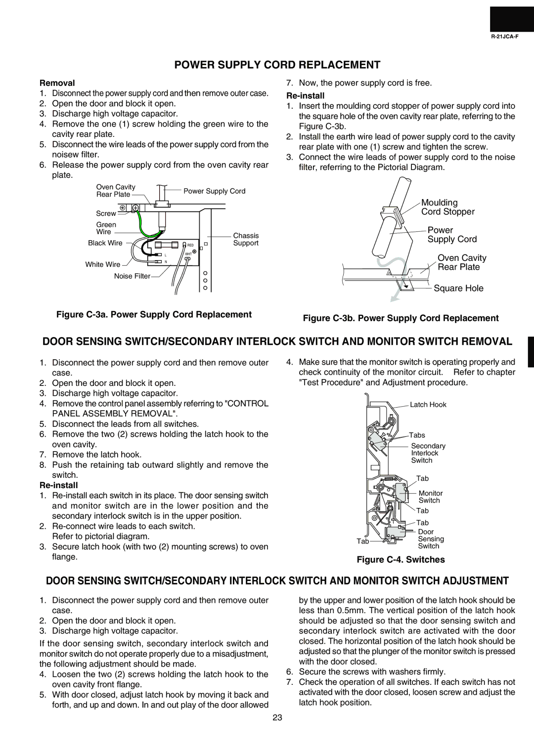
Figure C-3a. Power Supply Cord Replacement
7. Now, the power supply cord is free.
Re-install
1.Insert the moulding cord stopper of power supply cord into the square hole of the oven cavity rear plate, referring to the Figure
2.Install the earth wire lead of power supply cord to the cavity rear plate with one (1) screw and tighten the screw.
3.Connect the wire leads of power supply cord to the noise filter, referring to the Pictorial Diagram.
Moulding
Cord Stopper
Power
Supply Cord
Oven Cavity
Rear Plate
Square Hole
Figure C-3b. Power Supply Cord Replacement
DOOR SENSING SWITCH/SECONDARY INTERLOCK SWITCH AND MONITOR SWITCH REMOVAL
1.Disconnect the power supply cord and then remove outer case.
2.Open the door and block it open.
3.Discharge high voltage capacitor.
4.Remove the control panel assembly referring to "CONTROL PANEL ASSEMBLY REMOVAL".
5.Disconnect the leads from all switches.
6.Remove the two (2) screws holding the latch hook to the oven cavity.
7.Remove the latch hook.
8.Push the retaining tab outward slightly and remove the
switch.
1.
2.
3.Secure latch hook (with two (2) mounting screws) to oven flange.
4.Make sure that the monitor switch is operating properly and check continuity of the monitor circuit. Refer to chapter "Test Procedure" and Adjustment procedure.
Latch Hook
Tabs
Secondary
Interlock
Switch
Tab
![]()
![]() Monitor
Monitor
Switch
Tab
Tab
![]() Door
Door
Tab ![]()
![]() Sensing
Sensing
Switch
Figure C-4. Switches
DOOR SENSING SWITCH/SECONDARY INTERLOCK SWITCH AND MONITOR SWITCH ADJUSTMENT
1.Disconnect the power supply cord and then remove outer case.
2.Open the door and block it open.
3.Discharge high voltage capacitor.
If the door sensing switch, secondary interlock switch and monitor switch do not operate properly due to a misadjustment, the following adjustment should be made.
4.Loosen the two (2) screws holding the latch hook to the oven cavity front flange.
5.With door closed, adjust latch hook by moving it back and forth, and up and down. In and out play of the door allowed
by the upper and lower position of the latch hook should be less than 0.5mm. The vertical position of the latch hook should be adjusted so that the door sensing switch and secondary interlock switch are activated with the door closed. The horizontal position of the latch hook should be adjusted so that the plunger of the monitor switch is pressed with the door closed.
6.Secure the screws with washers firmly.
7.Check the operation of all switches. If each switch has not activated with the door closed, loosen screw and adjust the latch hook position.
23