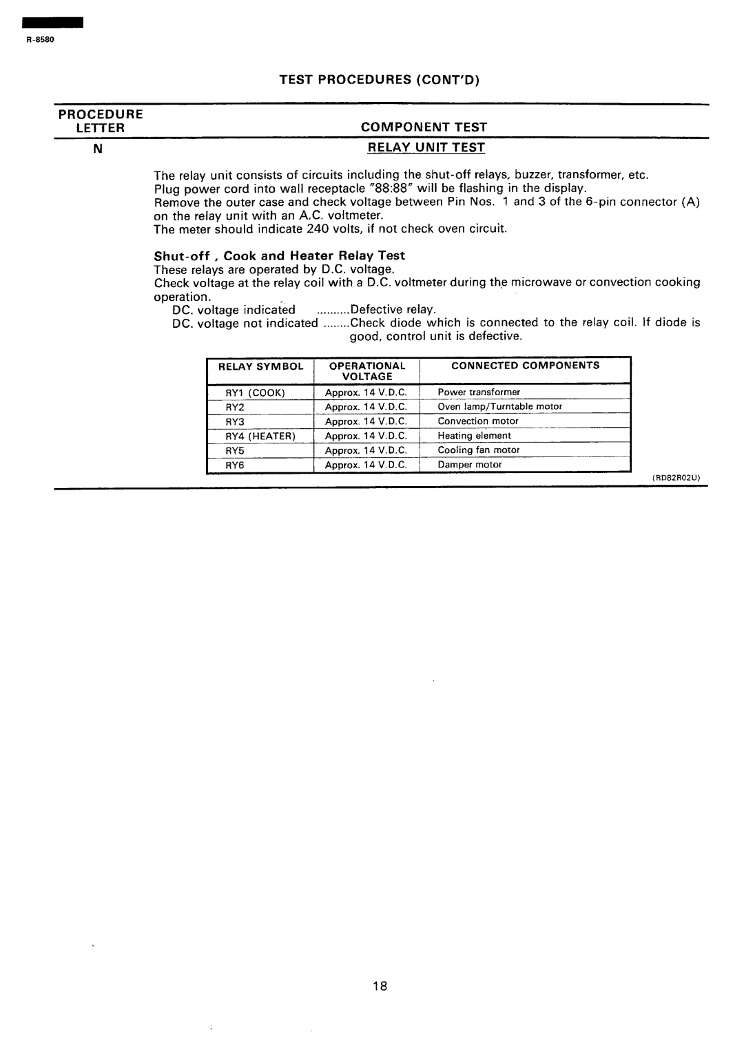
TEST | PROCEDURES | (CONT’O) | |
PROCEDURE |
|
|
|
LETTER | COMPONENT | TEST | |
N | RELAY | UNIT | TEST |
The relay unit consists of circuits including the
Remove the outer case and check voltage between Pin Nos. 1 and 3 of the
The meter should indicate 240 volts, if not check oven circuit.
Check voltage at the relay coil with a D.C. voltmeter during the microwave or convection cooking operation.
DC. voltage indicated .,........ Defective relay.
DC. voltage not indicated ........Check diode which is connected to the relay coil. If diode is
good, control unit is defective.
I | RELAY | SYMBOL |
| OPERATIONAL | CONNECTED COMPONENTS | ||||
|
| I | VOLTAGE |
|
| I | |||
| RYl | (COOK) |
| Approx. | 14 | V. D. C. | Power | transformer | |
| RY2 |
|
| Approx. | 14 | V.D.C. | Oven lamp/Turntable motor | ||
| RY3 |
|
| Approx. | 14 | V.D.C. | Convection | motor | |
| RY4 | (HEATER) |
| Approx. | 14 | V.D.C. | Heating | element | |
| RY5 |
|
| Approx. | 14 | V. D. C. | Cooling | fan | motor |
| RY6 |
|
| Aoorox. | 14 | V.D.C. | DamDer motor | ||
(RD82R02U)
18
