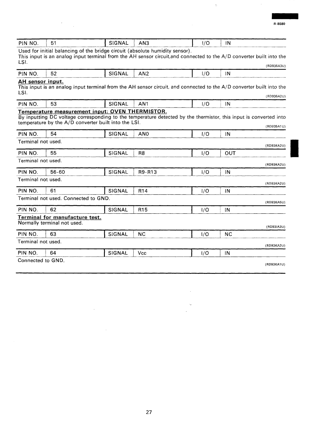
PIN NO. / 51 | 1 SIGNAL | / AN3 | I | I/O | / IN |
Used for initial balancing of the bridge circuit (absolute humidity sensor).
This input is an analog input terminal from the AH sensor circuit,and connected to the A/D converter built into the
(RD936A3U)
PIN | NO. | ( 52 | SIGNAL | / AN2 | I | I/O | IN |
|
|
|
|
|
|
| |
AH | sensor | inuut. |
|
|
|
|
|
This input is an analog input terminal from the AH sensor circuit, and connected to the A/D converter built into the LSI.
(RD936A2U)
PIN NO. | 1 53 | 1 SIGNAL | j AN1 | I | I/O |
Temperature measurement input: OVEN THERMISTOR.
By inputting DC voltage corresponding to the temperature detected by the thermistor, temperature by the A/D converter built into the LSI.
PIN NO. | 1 | 54 | 1 | SIGNAL | j | AN0 | I | I/O |
Terminal | not | used. |
|
|
|
|
|
|
PIN NO. | 1 | 55 | 1 | SIGNAL | j | R8 | I | I/O |
Terminal | not | used. |
|
|
|
|
|
|
j IN
this input is converted into
(RD935Al U)
j IN
(RD93KA2U)
/ OUT
(RD93KA2U)
PIN NO. | 1 | ) SIGNAL | / | I | l/O | 1 IN | ||||
Terminal | not | used. |
|
|
|
|
|
|
| |
|
|
|
|
|
| I | I/O |
| (RD93KA2U) | |
PIN NO. | ) | 61 | SIGNAL | j | RI4 | 1 IN | ||||
|
| |||||||||
Terminal not used. Connected to GND. |
|
|
|
|
|
| ||||
|
|
|
|
|
|
|
|
| (RD93KAW) | |
PIN NO. | 1 62 | 1 SIGNAL | j | RI5 | 1 | l/O | j | IN | ||
Terminal | for | manufacture | test. |
|
|
|
|
|
| |
Normally | terminal not used. |
|
|
|
|
|
|
| ||
|
|
|
|
|
|
|
|
| (RD93lA3U) | |
PIN NO. |
| 63 | 1 SIGNAL | 1 NC | I | I/O | / NC | |||
Terminal | not used. |
|
|
|
|
|
|
| ||
|
|
|
|
|
|
| l/O |
| (RD93KA2U) | |
PIN NO. | j | 64 | 1 SIGNAL | ) | vcc | I | j | IN | ||
Connected | to | GND. |
|
|
|
|
|
|
| |
(RD93KAl U)
27
