CONTROL PANEL ASSEMBLY AND CPU UNIT REMOVAL
The complete control panel should be removed for re- placement of components except the relay unit.
To remove the control panel, proceed as follows:
1, Disconnect oven from power supply and remove outer case.
2.Discharge the high voltage capacitor.
3.Disconnect the wire connectors and wire leads from the relay unit and CPU unit.
4.Disconnect a connector from the CPU unit.
5.Remove one (I ) screw holding the control panel back plate to the chassis support.
6.Remove the two (2) screws holding the bottom edge of the back plate to the cabinet base.
7.Remove one (I) screw holding the back plate to the oven cavity flange.
8.Lift up and pull the control panel forward.
Replacement of individual component is as follows:
CPU UNIT AND KEY UNIT
I, Disconnect the wire connector of CPU unit from the relay unit.
2.Remove the four (4) screws holding the panel frame to the back plate.
3.Separate the panel frame and back plate.
4.Remove the three (3) screws holding the CPU unit to the panel frame.
5.Lift up the control unit and disconnect the key connector from the CPU unit.
6.Now, the CPU unit and frame assembly are sepa- rated.
UPPER LATCH/LOWER LATCH/STOP SWITCHES AND MONITOR SWITCH ADJUSTMENT
If the upper latch,lower latch switches stop switch and monitor switch do not operate properly due to a
1.Loosen the one (1) screw holding the upper Jatch book to the oven cavity front flange and the one (1) screw holding the lower latch hook to the same flange.
2.With the door closed, adjust the lower latch book by moving it back and forth and then adjust the upper latch hook by moving it back and forth, or up and down. In and out play of the door allowed by the upper and lower latch hooks should be less than 0.5 mm. The vertical position of the upper latch hook should be placed where the upper latch switch and monitor switch have activated with the door closed. Vertical adjustment of the lower latch book is not possible.
3.Secure the screws with washers firmly.
4.Now, make sure of the upper latch switch opera- tion. If the upper latch switch has not, activated with the door closed, loose the one (1) screw holding the upper latch book to the oven cavity front flange and adjust the upper latch hook position.
After the adjustment, make sure of the following:
1.The in and out play of the door remains less than
0.5mm at latched position. First check the upper latch hook position, pushing and pulling the upper portion of door toward the oven face. Then check the lower latch hook position, pushing and pulling the lower portion of door toward the oven face. Both results (plays of the door) should be less than 0.5mm.
2.The upper latch and lower latch switches interrupt the circuit before the door can be opened.
3.The monitor switch contacts close when the door is opened.
4.
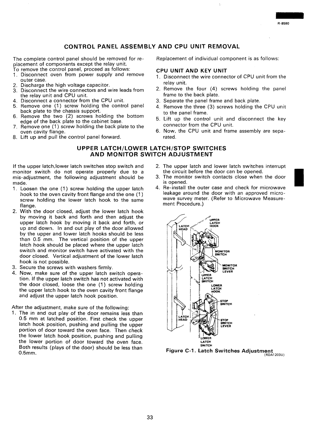
Figure C-l. Latch Switches Adjustment
(RDAl203U)
33