External Module Disassembly Process
NOTE: The product previews seen in the disassembly procedures may not represent the final product color or configuration.
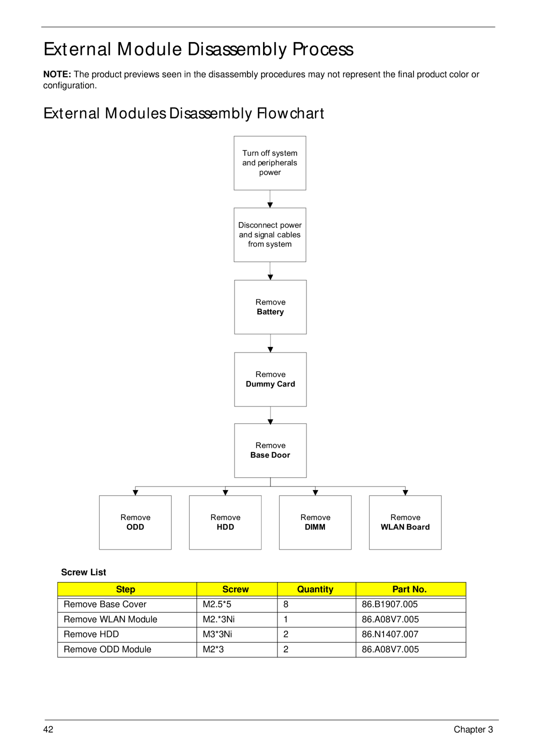
External Modules Disassembly Flowchart
Turn off system and peripherals power
Disconnect power and signal cables from system
Remove
Battery
Remove
Dummy Card
Remove
Base Door
Remove
ODD
Remove
HDD
Remove
DIMM
Remove
WLAN Board
Screw List
Step | Screw | Quantity | Part No. |
|
|
|
|
Remove Base Cover | M2.5*5 | 8 | 86.B1907.005 |
|
|
|
|
Remove WLAN Module | M2.*3Ni | 1 | 86.A08V7.005 |
|
|
|
|
Remove HDD | M3*3Ni | 2 | 86.N1407.007 |
|
|
|
|
Remove ODD Module | M2*3 | 2 | 86.A08V7.005 |
|
|
|
|
42 | Chapter 3 |