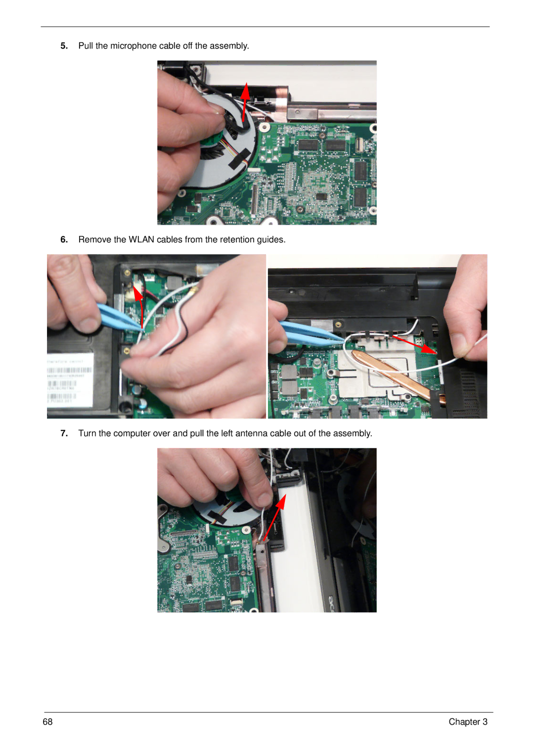
Manuals
/
Brands
/
Computer Equipment
/
Laptop
/
Acer
/
Computer Equipment
/
Laptop
Acer
5745
- page 78
1
78
233
233
Download
233 pages, 10.62 Mb
68
Chapter 3
5.
Pull the microphone cable off the assembly.
6.
Remove the WLAN cables from the retention guides.
7.
Turn the computer over and pull the le
ft antenna cable out of the assembly.
Contents
Main
Page
Copyright
Disclaimer
Conventions
Preface
Page
System Specifications 1
System Utilities 23
Machine Disassembly and Replacement 39
Troubleshooting 135
Page
Page
System Specifications
Chapter 1
Features
Operating System
Platform
Page
Special Keys and Controls
I/O Ports
Software
Optional Items
Warranty
Environment
Chapter 1 5
System Block Diagram
HDMI Con.
4
x
(
Notebook Tour
Top View
Closed Front View
Left View
Right View
Base View
Indicators
TouchPad Basics
Using the Keyboard
Lock Keys and embedded numeric keypad
Windows Keys
Hot Keys
Special Keys
Hardware Specifications and Configurations
Page
Page
Page
Page
Page
Page
Page
System Utilities
Chapter 2
BIOS Setup Utility
Navigating the BIOS Utility
Information
Main
Security
Page
Page
Boot
Exit
Page
DOS Flash Utility
Page
Remove HDD/BIOS Password Utilities
Page
Miscellaneous Utilities
Using Boot Sequence Selector
Using DMITools
Example 1: Read DMI Information from Memory
Example 2: Write Product Name to EEPROM
Using the LAN MAC Utility
Page
Machine Disassembly and Replacement
Chapter 3
Disassembly Requirements
Related Information
Replacement Requirements
Page
Disassembly Process
External Module Disassembly Process
External Modules Disassembly Flowchart
Removing the Battery Pack
Page
Removing the Base Door
Page
Page
Page
Page
Removing the WLAN Module
Page
Page
Page
Page
Chapter 3 55
Main Unit Disassembly Process
Main Unit Disassembly Flowchart
Page
Removing the Keyboard
Page
Page
Page
Page
Page
Page
Page
Page
Page
Page
Page
Page
Page
Page
Page
Page
Removing the Mainboard
Page
Removing the Thermal Module
Page
Page
Page
Page
LCD Module Disassembly Process
LCD Module Disassembly Flowchart
Page
Page
Page
Page
Removing the LCD Panel
Page
Page
Page
Page
Page
Page
LCD Reassembly Procedure
Replacing the Antennas
Page
Page
Page
Page
Page
Page
Page
Page
Page
Page
Page
Page
Page
Page
Replacing the Thermal Module
Page
Page
Page
Page
Page
Page
Page
Page
Page
Page
Page
Page
Page
Page
Page
Page
Page
Page
Page
Page
Page
Page
Page
Page
Page
Page
Troubleshooting
Chapter 4
Common Problems
Power On Issue
Computer Shuts down Intermittently
No Display Issue
No POST or Video
Abnormal Video Display
Random Loss of BIOS Settings
LCD Failure
Built-In Keyboard Failure
Chapter 4 141
TouchPad Failure
Internal Speaker Failure
Sound Problems
NG OK
Internal Microphone Failure
Microphone Problems
OK
NG
HDD Not Operating Correctly
USB Failure (Right up/down side)
Other Failures
Intermittent Problems
Undetermined Problems
POST Code Reference Tables
Page
Page
Page
Page
Page
Jumper and Connector Locations
Chapter 5
Mainboard Top View
Mainboard Bottom View
DIMM Socket Population Rules
BIOS Recovery
BIOS Recovery by Crisis Disk
BIOS Recovery Boot Block
BIOS Recovery Hotkey
Steps for BIOS Recovery from USB Storage
FRU (Field Replaceable Unit) List
Chapter 6
Exploded Diagrams
Main Assembly
Page
LCD Assembly
FRU List
Page
Page
Page
Page
Page
Page
Screw List
Model Definition and Configuration
Appendix A
Page
Page
Page
Page
Page
Page
Page
Page
Page
Page
Page
Page
Page
Page
Page
Page
Page
Page
Page
Page
Page
Page
Page
Page
Page
Page
Page
Page
Page
Page
Page
Page
Page
Page
Page
Page
Page
Page
Page
Page
Page
Page
Page
Page
Page
Test Compatible Components
Appendix B
Page
Page
Page
Online Support Information
Appendix C
Page
A
Index
B
C
D
N
O
P
S
T