TEST PROCEDURES (CONT’D)
PROCEDURE |
|
|
LETTER | COMPONENT | TEST |
CHECKING CONTROL UNIT
(1)Disconnect oven from power supply and remove outer case.
(2)Discharge the high voltage capacitor.
(3)Disconnect the wire leads from the cook relay.
(4)Disconnect the sensor connector that is mounted to lower position of control panel.
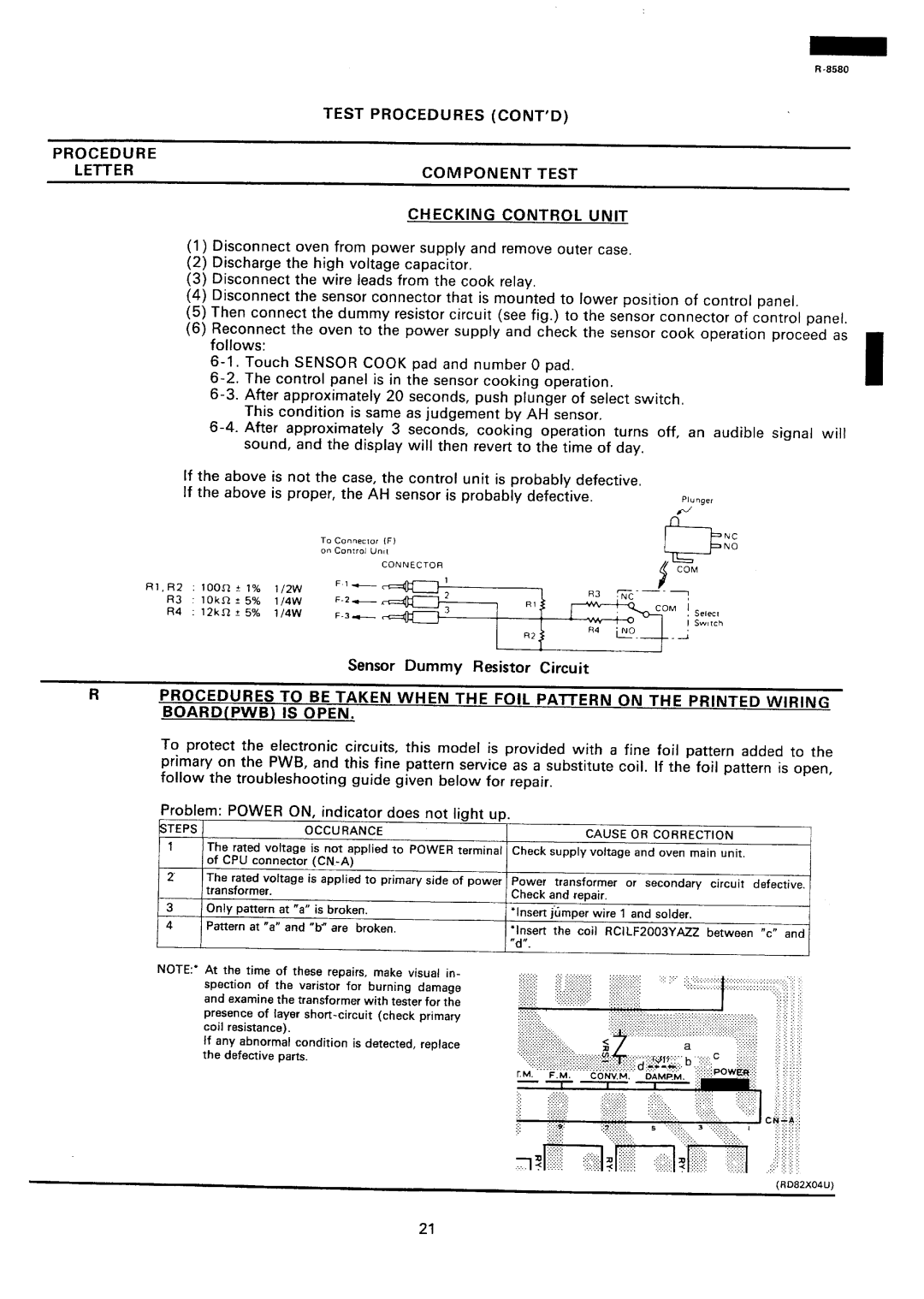
(5)Then connect the dummy resistor circuit (see fig.) to the sensor connector of control panel.
(6)Reconnect the oven to the power supply and check the sensor cook operation proceed as follows:
If the above is not the case, the control unit is probably defective. If the above is proper, the AH sensor is probably defective.
|
|
|
| To | Connector | (F) |
|
|
|
| on | Control | Untt |
|
|
|
|
|
| CONNECTOR |
Rl, R2 | : loon | t | 1% | 1/2w |
| |
|
| |||||
R3 | : 10kR | ? 5% | 1/4W |
| ||
R4 | : 12kR | * | 5% | 1/4W |
| |
R4
R2iNO.
Plunger
NC
NO
I Switch
Sensor Dummy Resistor Circuit
RPROCEDURES TO BE TAKEN WHEN THE FOIL PATTERN ON THE PRINTED WIRING
BOARD(PWB) IS OPEN.
To protect the electronic circuits, this model is provided with a fine foil pattern added to the primary on the PWB, and this fine pattern service as a substitute coil. If the foil pattern is open,
follow the troubleshooting guide given below for repair.
Problem: POWER CJN, indicator does not light up.
STEPS | OCCURANCE | CAUSE OR CORRECTION |
1The rated voltage is not applied to POWER terminal Check supply voltage and oven main unit. of CPU connector
2 The rated voltage is applied to primarv side of Dower Power transformer or secondarv circuit defective.
NOTE:* At the time of these repairs, make visual in- spection of the varistor for burning damage and examine the transformer with tester for the presence of layer
If any abnormalcondition is detected, replace the defective parts.
21