Connecting Pin Assignments (Continued)
|
|
|
|
|
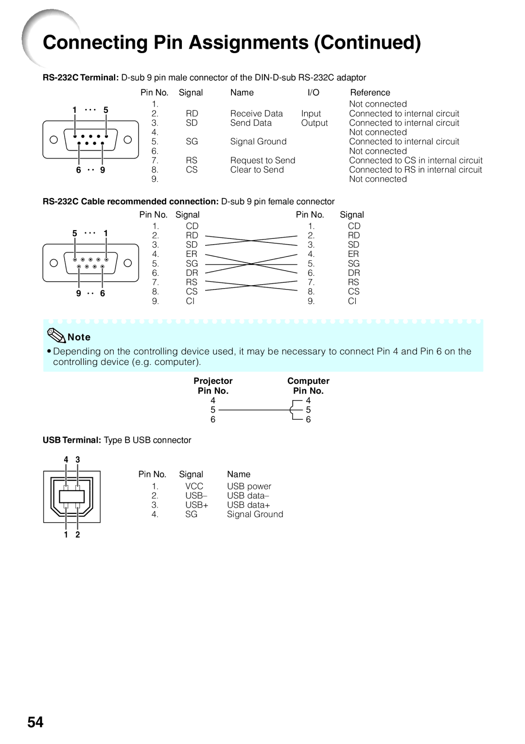
| Pin No. | Signal | Name | I/O | Reference |
1 |
| 5 | 1. |
| Receive Data | Input | Not connected | |||
| 2. | RD | Connected to internal circuit | |||||||
|
|
|
|
|
| 3. | SD | Send Data | Output | Connected to internal circuit |
|
|
|
|
|
| 4. |
| Signal Ground |
| Not connected |
|
|
|
|
|
|
|
| |||
|
|
|
|
|
| 5. | SG |
| Connected to internal circuit | |
|
|
|
|
|
| 6. |
|
|
| Not connected |
|
|
|
|
|
| 7. | RS | Request to Send |
| Connected to CS in internal circuit |
6 | 9 |
| 8. | CS | Clear to Send |
| Connected to RS in internal circuit | |||
|
|
|
|
|
| 9. |
|
|
| Not connected |
|
| Pin No. | Signal | Pin No. | Signal |
5 | 1 | 1. | CD | 1. | CD |
2. | RD | 2. | RD | ||
|
| 3. | SD | 3. | SD |
|
| 4. | ER | 4. | ER |
|
| 5. | SG | 5. | SG |
|
| 6. | DR | 6. | DR |
|
| 7. | RS | 7. | RS |
9 | 6 | 8. | CS | 8. | CS |
|
| 9. | CI | 9. | CI |
![]() Note
Note
•Depending on the controlling device used, it may be necessary to connect Pin 4 and Pin 6 on the controlling device (e.g. computer).
Projector | Computer | ||||||
Pin No. |
| Pin No. | |||||
4 |
|
|
|
|
| 4 | |
5 |
|
|
|
|
|
| 5 |
|
|
|
|
|
| ||
6 |
|
|
|
|
|
| 6 |
USB Terminal: Type B USB connector |
| |||||||
4 | 3 |
|
|
|
| |||
|
|
|
|
|
| Pin No. | Signal | Name |
|
|
|
|
|
| |||
|
|
|
|
|
| 1. | VCC | USB power |
|
|
|
|
|
| 2. | USB– | USB data– |
|
|
|
|
|
| 3. | USB+ | USB data+ |
|
|
|
|
|
| |||
|
|
|
|
|
| 4. | SG | Signal Ground |
|
|
|
|
|
|
|
|
|
|
|
|
|
|
|
|
|
|
1 2
54