Setup
Features
XR-32X-L XR-32S-L
OPERATION MANUAL
Model No Serial No
SPECIAL NOTE FOR USERS IN THE U.K
DANGER
The supplied CD-ROM contains operation instructions in English, German, French, Spanish, Italian, Dutch, Swedish, Portuguese, Chinese, Korean and Arabic. Carefully read through the operation instructions before operating the projector
1. WARRANTY
2. CONSUMER PRODUCT SAFETY ACT
Introduction
IntroductionENGLISH
Caution Concerning Lamp Replacement
INFORMATION
Declaration of conformity
PRODUCT DISPOSAL
Maintenance
Troubleshooting
For Future Reference
Index
Contents
Using
Setup
Useful Features
Reference
Appendix
IMPORTANT SAFEGUARDS
5. Cleaning
8. Accessories
11. Power Sources
18. Damage Requiring Service
19. Replacement Parts
20. Safety Check
15. Overloading
Observe the following safeguards when setting up your projector
Caution concerning the setup of the projector
Caution concerning the lamp unit
Warning about placing the projector in a high position
How to Access the PDF Operation Manuals
Info
Using the projector in other countries
Accessing the PDF Manuals for Windows For Macintosh, skip step
Accessories
Supplied accessories
Optional accessories
Part Names and Functions
Projector
Introduction
Top View
Part Names and Functions Continued
Rear View
Using the Kensington Lock
Terminals
For selecting and adjusting menu items
For moving the
For the Left click
For changing the pointer or spot
Inserting the Batteries
2 Insert the batteries
Usable Range
Setup and Projection
Quick Start
1. Place the projector facing a wall or a screen
3. Remove the lens cap and turn the projector on
4. Adjust the projected image with the Setup Guide
7. Turn the computer on 8. Turn the power off
5. Correct trapezoidal distortion
6. Select the INPUT mode
Setting up the Projector
Setting up the Projector
Standard Setup Front Projection
Ceiling-mount Setup
Setup
Projection PRJ Mode
Indication of the Projection Image Size and Projection Distance
Setting up the Projector Continued
Screen Size and Projection Distance
NORMAL Mode
STRETCH Mode
Connecting the Projector to Other Equipment
Terminals on the Projector
Connections
Example Terminals of XR-32X
Connecting the Projector to Other Equipment Continued
Connections
Connecting the Power Cord
Controlling the Projector by a Computer
Plug the supplied power cord into the
AC socket on the rear of the projector Then plug into AC outlet
Turning the Projector On/Off
Turning the Projector on
OperationBasic
Turning the Power off Putting the Projector into Standby Mode
About the Setup Guide
Adjusting the Projected Image 1 Adjusting the Focus
2 Adjusting the Picture Size
Image Projection
3 Adjusting the Height
Image Projection Continued
Correcting Trapezoidal Distortion
2 Press P/Q or O/R to adjust the Keystone Correction
1 Press KEYSTONE to enter the Keystone Correction mode
Switching the Input Mode
Adjusting the Volume
Displaying the Black Screen and Turning off the Sound Temporarily
Press VOL +/- on the remote control or
Resize Mode
COMPUTER
Press RESIZE
About Copyrights
VIDEO/DTV
Operating with the Remote Control
Displaying and Setting the Break Timer
Using the Spot Function
Switching the Eco+Quiet Mode
Auto Sync Auto Sync Adjustment
Freezing a Moving Image
Selecting the Picture Mode
Displaying an Enlarged Portion of an Image
Operating with the Remote Control Continued
Using the Remote Control as the Wireless Computer Mouse
Connecting with a USB cable
Menu Items
The following shows the items that can be set in the projector
“Picture” menu
“C.M.S.”
Menu Items Continued
“Screen adjustment SCR-ADJ” menu
“Projector adjustment PRJ-ADJ” menu
The items you can set with the “Help” menu
“Help” menu
Using the Menu Screen
Menu Selections Adjustments
2 Press Q or O and select “Picture” to adjust
1 Press MENU/HELP
To adjust the projected image while watching it
3 Press P or R and select “Bright” to adjust
4 Press O or Q to adjust the item selected
Press ENTER
Picture Adjustment “Picture” Menu
1 Selecting the Picture Mode
2Adjusting the Image
3Adjusting the Color Temperature
4Adjusting the Colors
ENTER
Picture Adjustment “Picture” Menu Continued
7Lamp Setting
5 Progressive
6 Reducing Image Noise DNR
Adjusting the Projected Image “SCR - ADJ” Menu
1 Setting the Resize Mode
2 Adjusting the Image Position
4 Setting the On-screen Display
Adjusting the Projected Image “SCR - ADJ” Menu Continued
6 Selecting the Setup Guide
5 Selecting the Background Image
7 Reversing/Inverting Projected Images
Adjusting the Projector Function “PRJ - ADJ” Menu
Adjustment
2 Auto Power Off Function
5 Setting the Confirmation
9 Fan Mode Setting
a Setting/Changing the keycode
7 Audio Input XR-32X only
0 System Lock Function
Keylock Function
Checking the Lamp Life Status
Locking the Operation Buttons on the Projector
5 Enter the same keycode in “Re- confirm”
Troubleshooting with the “Help” Menu
Utilizing the “Help” Menu Functions
6 Press O or Q to adjust
2 Press Oor Qto select “Help”, then press ENTER
Maintenance
Appendix
Cleaning the projector
Cleaning the lens
Maintenance Indicators
About the temperature warning indicator
About the lamp indicator
If the temperature warning indicator illuminates, and the projector enters standby mode, follow the possible solutions above and then wait until the projector has cooled down completely before plug- ging in the power cord and turning the power back on. At least 10 minutes
Regarding the Lamp
Lamp
Hg LAMP CONTAINS MERCURY For State Lamp Disposal
Information
Removing and Installing the Lamp Unit
2 Disconnect the power cord
3 Remove the lamp unit cover
Lamp unit
Resetting the Lamp Timer
Regarding the Lamp Continued
1 Connect the power cord
2 Reset the lamp timer
Connecting Pin Assignments
sub 15 pin female connector
DVI-D Terminal 24 pin connector XR-32X only
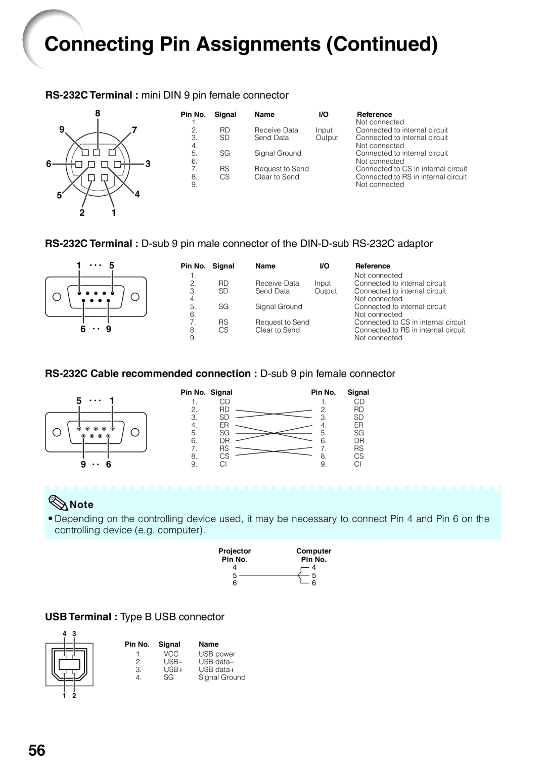
Connecting Pin Assignments Continued
RS-232C Cable recommended connection D-sub 9 pin female connector
RS-232C Specifications and Commands
Computer control
Communication conditions
Basic format
RS-232C Specifications and Commands Continued
Commands
Example When turning on the projector, make the following setting
P O W R
Appendix
RS-232C Specifications and Commands Continued
is only for XR-32X
Appendix
Computer Compatibility Chart
Computer
Troubleshooting
21-24
Troubleshooting Continued
using STANDBY/ON on
49, 50
For SHARP Assistance
Specifications
Dimensions
Units inches mm
Index
33, 37, 45
COMPUTER/COMPONENT input terminal