Assembly
Driveshaft and Powerhead
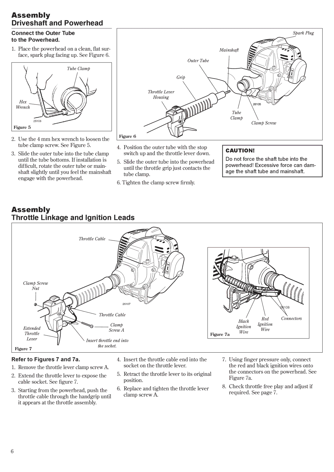
Connect the Outer Tube to the Powerhead.
1.Place the powerhead on a clean, flat sur- face, spark plug facing up. See Figure 6.
Tube Clamp
Hex
Wrench
Figure 5
2.Use the 4 mm hex wrench to loosen the tube clamp screw. See Figure 5.
3.Slide the outer tube into the tube clamp until the tube bottoms. If installation is difficult, rotate the outer tube or main- shaft slightly until you feel the mainshaft engage with the powerhead.
Spark Plug
Mainshaft
Outer Tube
Grip |
| |
Throttle Lever |
| |
Housing |
| |
| 26105 | |
| Tube | |
| Clamp | |
| Clamp Screw | |
Figure 6 |
| |
4. Position the outer tube with the stop | CAUTION! | |
switch up and the throttle lever down. | ||
Do not force the shaft tube into the | ||
5. Slide the outer tube into the powerhead | ||
powerhead! Excessive force can dam- | ||
until the throttle grip just contacts the | ||
age the shaft tube and mainshaft. | ||
tube clamp. | ||
|
6. Tighten the clamp screw firmly.
Assembly
Throttle Linkage and Ignition Leads
| Throttle Cable |
|
|
|
|
Clamp Screw |
|
|
|
|
|
Nut |
|
|
|
|
|
| 26107 |
|
|
|
|
| Throttle Cable |
|
| Red | Connectors |
|
|
| Black | ||
| Clamp |
| Ignition |
| |
Extended |
| Ignition |
| ||
Screw A |
| Wire |
| ||
| Wire |
| |||
Throttle |
| Figure 7a |
|
| |
|
|
|
| ||
Lever | Insert throttle end into |
|
|
|
|
|
|
|
|
| |
Figure 7 | the socket. |
|
|
|
|
|
|
|
|
|
Refer to Figures 7 and 7a.
1.Remove the throttle lever clamp screw A.
2.Extend the throttle lever to expose the cable socket. See figure 7.
3.Starting from the powerhead, push the throttle cable through the handgrip until it appears at the throttle assembly.
4.Insert the throttle cable end into the socket on the throttle lever.
5.Retract the throttle lever to its original position.
6.Replace and tighten the throttle lever clamp screw A.
7.Using finger pressure only, connect the red and black ignition wires onto the connectors on the powerhead. See Figure 7a.
8.Check throttle free play and adjust if required. See page 7.