Assembly
Attachment Shield and Edger Blade
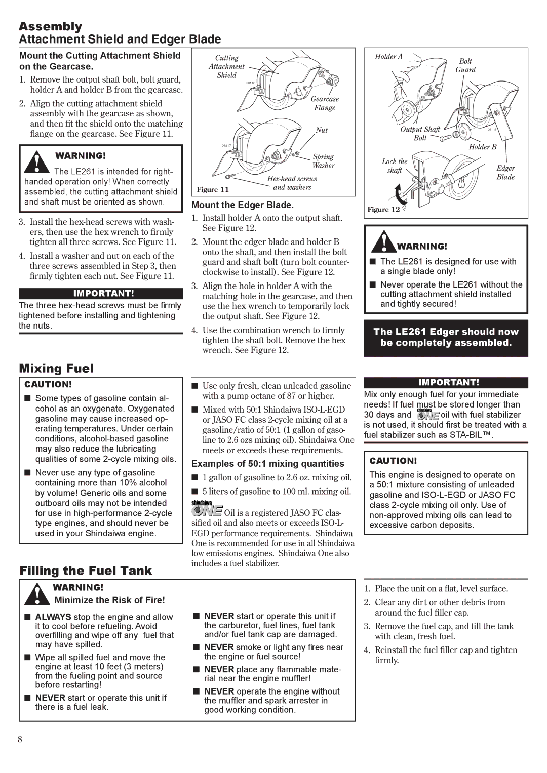
Mount the Cutting Attachment Shield on the Gearcase.
1.Remove the output shaft bolt, bolt guard, holder A and holder B from the gearcase.
2.Align the cutting attachment shield assembly with the gearcase as shown, and then fit the shield onto the matching flange on the gearcase. See Figure 11.
WARNING!
The LE261 is intended for right- handed operation only! When correctly assembled, the cutting attachment shield
Cutting
Attachment
Shield
26116
26117
Figure 11
![]() Gearcase Flange
Gearcase Flange
Nut
![]()
![]()
![]()
![]()
![]()
![]() Spring
Spring
Washer
and washers
Holder A | Bolt |
| |
| Guard |
Output Shaft | 26118 |
Bolt | Holder B |
| |
Lock the | Edger |
shaft | |
| Blade |
and shaft must be oriented as shown.
3.Install the
4.Install a washer and nut on each of the three screws assembled in Step 3, then firmly tighten each nut. See Figure 11.
IMPORTANT!
The three
Mount the Edger Blade.
1.Install holder A onto the output shaft. See Figure 12.
2.Mount the edger blade and holder B onto the shaft, and then install the bolt guard and shaft bolt (turn bolt counter- clockwise to install). See Figure 12.
3.Align the hole in holder A with the matching hole in the gearcase, and then use the hex wrench to temporarily lock the output shaft. See Figure 12.
4.Use the combination wrench to firmly tighten the shaft bolt. Remove the hex wrench. See Figure 12.
Figure 12 |
![]() WARNING!
WARNING!
nThe LE261 is designed for use with a single blade only!
nNever operate the LE261 without the cutting attachment shield installed and tightly secured!
The LE261 Edger should now be completely assembled.
Mixing Fuel
CAUTION!
nSome types of gasoline contain al- cohol as an oxygenate. Oxygenated gasoline may cause increased op- erating temperatures. Under certain conditions,
nNever use any type of gasoline containing more than 10% alcohol by volume! Generic oils and some outboard oils may not be intended for use in
Filling the Fuel Tank
nUse only fresh, clean unleaded gasoline with a pump octane of 87 or higher.
nMixed with 50:1 Shindaiwa
Examples of 50:1 mixing quantities
n1 gallon of gasoline to 2.6 oz. mixing oil.
n5 liters of gasoline to 100 ml. mixing oil.
![]() Oil is a registered JASO FC clas- sified oil and also meets or exceeds
Oil is a registered JASO FC clas- sified oil and also meets or exceeds
IMPORTANT!
Mix only enough fuel for your immediate needs! If fuel must be stored longer than
30 days and oil with fuel stabilizer is not used, it should first be treated with a fuel stabilizer such as
CAUTION!
This engine is designed to operate on a 50:1 mixture consisting of unleaded gasoline and
WARNING!
Minimize the Risk of Fire!
1. | Place the unit on a flat, level surface. |
2. | Clear any dirt or other debris from |
nALWAYS stop the engine and allow it to cool before refueling. Avoid overfilling and wipe off any fuel that may have spilled.
nWipe all spilled fuel and move the engine at least 10 feet (3 meters) from the fueling point and source before restarting!
nNEVER start or operate this unit if there is a fuel leak.
nNEVER start or operate this unit if the carburetor, fuel lines, fuel tank and/or fuel tank cap are damaged.
nNever smoke or light any fires near the engine or fuel source!
nNever place any flammable mate- rial near the engine muffler!
nNever operate the engine without the muffler and spark arrester in good working condition.
| around the fuel filler cap. |
3. | Remove the fuel cap, and fill the tank |
| with clean, fresh fuel. |
4. | Reinstall the fuel filler cap and tighten |
| firmly. |