GROUNDING
If there should be objectional hum, ground the metal chassis of the mixer to a good ground such as a metal frame of a wall outlet or a water or steam pipe.
INPUT CONNECTIONS
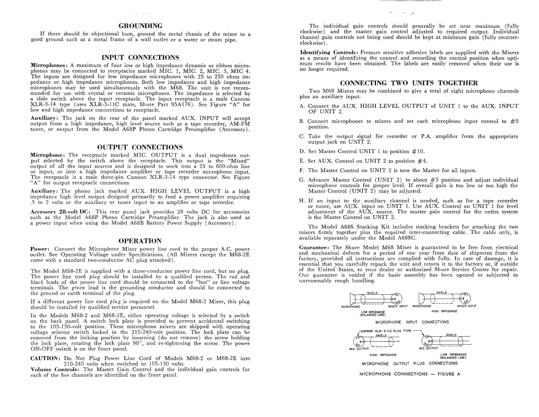
Microphones: A maximum of four low or high impedance dynamic or ribbon micro- phones may be connected to receptacles marked MIC. 1, MIC. 2, MIC. 3, M I C 4. The inputs are designed for low impedance microphones with 25 to 250 ohms im- pedance or high impedance microphones. Both low impedance and high impedance microphones may be used simultaneously with the M68. The unit is not recom- mended for use with crystal or ceramic microphones. The impedance is selected by a slide switch above the input receptacle. The input receptacle is a male Cannon XLR-3-14 type (uses XLR-3-11C mate, Shure Part 95A-3176). See Figure “A” for low and high impedance connections to receptacle.
Auxiliary: The jack on the rear of the panel marked AUX. INPUT will accept output from a high impedance, high level source such as a tape recorder, AM-FM tuner, or output from the Model A68P Phono Cartridge Preamplifier (Accessory).
OUTPUT CONNECTIONS
Microphone: The receptacle marked MIC. O U T P U T is a dual impedance out- put selected by the switch above the receptacle. This output is the “Mixed” output of all the input sources and is designed to work into a 25 to 600-ohm line or input, or into a high impedance amplifier or tape recorder microphone input. The receptacle is a male three-pin Cannon XLR-3-14 type connector. See Figure “A” for output receptacle connections.
Auxiliary: The phono jack marked AUX. HIGH LEVEL O U T P U T is a high impedance high level output designed primarily to feed a power amplifier requiring
.5 to 2 volts or the auxiliary or tuner input to an amplifier or tape recorder.
Accessory 28-voltDC: This rear panel jack provides 28 volts DC for accessories such as the Model A68P Phono Cartridge Preamplifier. The jack is also used as a power input when using the Model A68B Battery Power Supply (Accessory).
OPERATION
Power: Connect the Microphone Mixer power line cord to the proper A.C. power outlet. See Operating Voltage under Specifications. (All Mixers except the M68-2E come with a standard two-conductor AC plug attached).
The Model M68-2E is supplied with a three-conductor power line cord, but no plug. The power line cord p l u g should be installed by a qualified person. The red and black leads of the power line cord should be connected to the “hot” or line voltage terminals. The green lead is the grounding conductor and should be connected to the ground or earth terminal of the plug.
If a different power line cord p l u g is required on the Model M68-2 Mixer, this plug should be installed by qualified service personnel.
I n the Models M68-2 and M68-2E, either operating voltage is selected by a switch on the back panel. A switch lock plate is provided to prevent accidental switching to the 105-130-volt position. These microphone mixers are shipped with operating voltage selector switch locked in the 210-240-volt position. The lock plate can be removed from the locking position by loosening (do not remove) the screw holding the lock plate, rotating the lock plate go”, and re-tightening the screw. The power ON-OFF switch is on the front panel.
CAUTION: Do Not Plug Power Line Cord of Models M68-2 or M68-2E into 210-240 volts when switched to 105-130 volts.
Volume Controls: The Master Gain Control and the individual gain controls for each of the five channels are identified on the front panel.
The individual gain controls should generally be set near maximum (fully clockwise) and the master gain control adjusted to required output. Individual channel gain controls not being used should be kept a t minimum gain (fully counter- clockwise).
Identifying Controls : Pressure sensitive adhesive labels are supplied with the Mixers as a means of identifying the control and recording the control position when opti- mum results have been obtained. The labels are easily removed when their use is no longer required.
CONNECTING TWO UNITS TOGETHER
Two M68 Mixers may be combined to give a total of eight microphone channels plus an auxiliary input.
A.Connect the AUX. HIGH LEVEL O U T P U T of U N I T 1 to the AUX. INPUT O F U N I T 2.
B.Connect microphones to mixers and set each microphone input control to #O position.
C.Take the output signal for recorder or P.A. amplifier from the appropriate output jack on U N I T 2.
D.Set Master Control U N I T 1 to position #lo .
E.Set AUX. Control on U N I T 2 to position #4.
F.The Master Control on U N I T 2 is now the Master for all inputs.
G.Advance Master Control ( U N I T 2) to about #5 position and adjust individual microphone controls for proper level. If overall gain is too low or too high the Master Control ( U N I T 2 ) may be adjusted.
H . If an input to the auxiliary channel is needed, such as for a tape recorder or tuner, use AUX. input on U N I T 1. Use AUX. Control on U N I T 1 for level adjustment of the AUX. source. The master gain control for the entire system is the Master Control on U N I T 2.
The Model A68S Stacking Kit includes stacking brackets for attaching the two mixers firmly together plus the required inter-connecting cable. The cable only, is available separately under the Model A68SC.
Guarantee: The Shure Model M68 Mixer is guaranteed to be free from electrical and mechanical defects for a period of one year from date of shipment from the factory, provided all instructions are complied with fully. In case of daamge, it is essential that you carefully repack the unit and return it to the factory or, if outside of the United States, to your dealer or authorized Shure Service Center for repair. Our guarantee is voided if the basic assembly has been opened or subjected to unreasonably rough handling.
| SHIELD |
- ____ - | MIXER INPUT MICROPHONE | MIXER INPUT |
MICROPHONE |
[BALANCEDLOWIMPEDANCELINE1 | HIGH | IMPEDANCE |
MICROPHONE INPUT CONNECTIONS |
| - _ _ _ _ _ |
MIC. OUTPUT | MIC. OUTPUT |
HIGH IMPEDANCE | LOW IMPEDANCE |
| (BALANCED LINE1 |
MICROPHONE OUTPUT | PLUG CONNECTIONS |
MICROPHONE CONNECTIONS - FIGURE A