SECTION 18. ADJUSTING
BLOWER SPEED
Determine initial heating and cooling speeds in system design stage. See Specification Sheet for airflow data. Depending on tests performed in following sections, you may need to change blower motor speed.
CAUTION: Heating speed tap should not be reduced below factory setting. Doing so may result in inadequate air circulation, and could cause excessive air temperature rise through furnace. This could cause a
All models have these four motor speed designations:
High Speed (HI) | Black wire |
Medium High Speed (MH) | Blue wire |
Medium Low Speed (ML) | Yellow wire |
Low Speed (LO) | Red wire |
![]() WARNING: To prevent electric shock, turn off electrical power to furnace before changing blower motor
WARNING: To prevent electric shock, turn off electrical power to furnace before changing blower motor
speed.
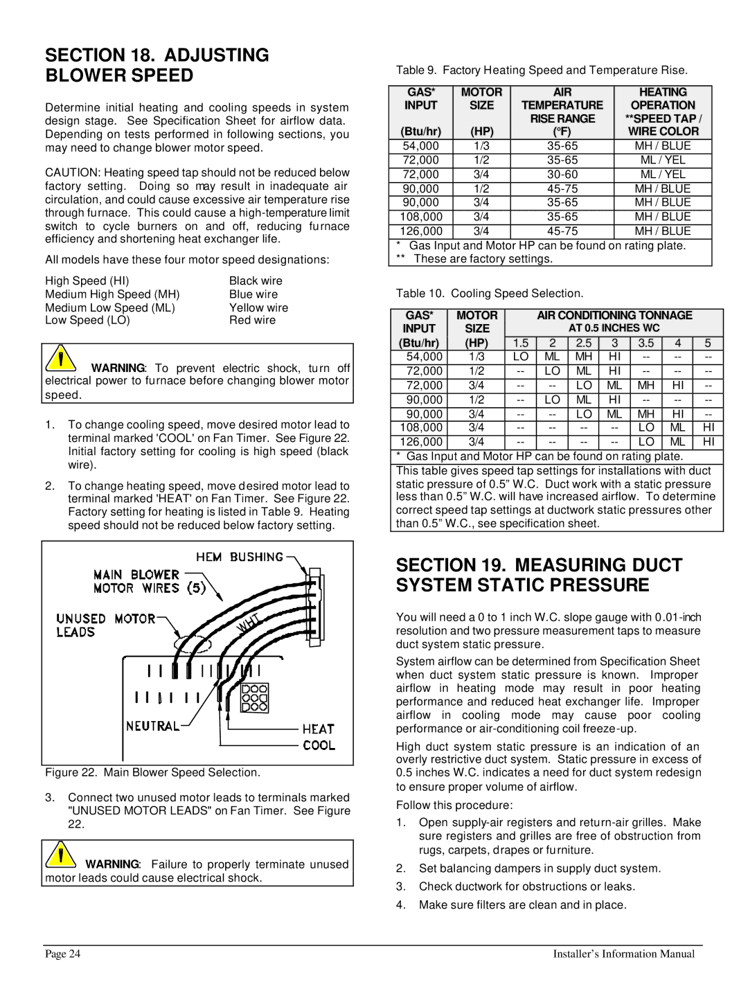
1.To change cooling speed, move desired motor lead to terminal marked 'COOL' on Fan Timer. See Figure 22. Initial factory setting for cooling is high speed (black wire).
2.To change heating speed, move desired motor lead to terminal marked 'HEAT' on Fan Timer. See Figure 22. Factory setting for heating is listed in Table 9. Heating speed should not be reduced below factory setting.
Table 9. Factory Heating Speed and Temperature Rise.
|
| GAS* |
|
| MOTOR |
|
|
| AIR |
|
|
|
|
| HEATING |
|
| |||
|
| INPUT |
|
| SIZE |
| TEMPERATURE |
|
|
| OPERATION |
|
| |||||||
|
|
|
|
|
|
|
| RISE RANGE |
|
| **SPEED TAP / |
|
| |||||||
|
| (Btu/hr) |
|
| (HP) |
|
|
| (°F) |
|
|
|
| WIRE COLOR |
|
| ||||
|
| 54,000 |
|
| 1/3 |
|
|
|
|
|
| MH / BLUE |
|
| ||||||
|
| 72,000 |
| 1/2 |
|
|
|
|
|
| ML / YEL |
|
| |||||||
|
| 72,000 |
| 3/4 |
|
|
|
|
|
| ML / YEL |
|
| |||||||
|
| 90,000 |
| 1/2 |
|
|
|
|
|
| MH / BLUE |
|
| |||||||
|
| 90,000 |
| 3/4 |
|
|
|
|
|
| MH / BLUE |
|
| |||||||
|
| 108,000 |
| 3/4 |
|
|
|
|
|
| MH / BLUE |
|
| |||||||
|
| 126,000 |
| 3/4 |
|
|
|
|
|
| MH / BLUE |
|
| |||||||
|
| * Gas Input | and Motor HP can be found on rating plate. |
|
| |||||||||||||||
|
| ** These are factory settings. |
|
|
|
|
|
|
|
|
|
| ||||||||
|
| Table 10. Cooling Speed Selection. |
|
|
|
|
|
|
|
| ||||||||||
|
|
|
|
|
|
|
|
|
|
|
|
|
|
|
|
| ||||
|
| GAS* |
| MOTOR |
|
|
| AIR CONDITIONING TONNAGE |
|
| ||||||||||
|
| INPUT |
|
| SIZE |
|
|
|
| AT 0.5 INCHES WC |
|
|
|
| ||||||
|
| (Btu/hr) |
|
| (HP) |
| 1.5 |
| 2 |
| 2.5 |
| 3 |
| 3.5 | 4 |
| 5 |
| |
|
| 54,000 |
| 1/3 |
| LO |
| ML |
| MH |
| HI |
|
|
| |||||
|
| 72,000 | 1/2 |
| LO |
| ML |
| HI |
|
|
| ||||||||
|
| 72,000 | 3/4 |
|
| LO |
| ML |
| MH | HI |
|
| |||||||
|
| 90,000 | 1/2 |
| LO |
| ML |
| HI |
|
|
| ||||||||
|
| 90,000 | 3/4 |
|
| LO |
| ML |
| MH | HI |
|
| |||||||
|
| 108,000 | 3/4 |
|
|
|
| LO | ML |
| HI | |||||||||
|
| 126,000 | 3/4 |
|
|
|
| LO | ML |
| HI | |||||||||
* Gas Input and Motor HP can be found on rating plate.
This table gives speed tap settings for installations with duct static pressure of 0.5” W.C. Duct work with a static pressure less than 0.5” W.C. will have increased airflow. To determine correct speed tap settings at ductwork static pressures other than 0.5” W.C., see specification sheet.
Figure 22. Main Blower Speed Selection.
3.Connect two unused motor leads to terminals marked "UNUSED MOTOR LEADS" on Fan Timer. See Figure 22.
![]() WARNING: Failure to properly terminate unused motor leads could cause electrical shock.
WARNING: Failure to properly terminate unused motor leads could cause electrical shock.
SECTION 19. MEASURING DUCT SYSTEM STATIC PRESSURE
You will need a 0 to 1 inch W.C. slope gauge with
System airflow can be determined from Specification Sheet when duct system static pressure is known. Improper airflow in heating mode may result in poor heating performance and reduced heat exchanger life. Improper airflow in cooling mode may cause poor cooling performance or
High duct system static pressure is an indication of an overly restrictive duct system. Static pressure in excess of
0.5inches W.C. indicates a need for duct system redesign to ensure proper volume of airflow.
Follow this procedure:
1.Open
2.Set balancing dampers in supply duct system.
3.Check ductwork for obstructions or leaks.
4.Make sure filters are clean and in place.
Page 24 | Installer’s Information Manual |