SECTION 11. CHECKS BEFORE STARTING FURNACE
Before starting furnace for the first time, be sure you can answer "Yes" to each of these questions:
1.Is furnace properly equipped to operate with available fuel?
2.Is furnace level?
3.Have you cleared away all loose construction and insulation materials?
4.Is furnace installed with proper clearances?
5.Does furnace have sufficient combustion and ventilation air?
6.Is the vent system sloped toward the furnace at least 1/4 inch per foot?
7.Have you checked the vent system for leaks?
8.Did you completely check gas pipe and controls for gas leaks?
9.Does electrical wiring follow current National Electrical Code ANSI/NFPA 70 or Canadian Electrical Code CSA C22.1 as well as local codes?
10.Is furnace electrically grounded?
11.Is room thermostat properly installed and heat anticipator set correctly?
12.Is duct system correctly sized and sealed?
13.Are proper air filter cabinets installed?
14.Are air filters in place and correctly sized?
SECTION 12. GAS SUPPLY PRESSURE AND PILOT ADJUSTMENT
You will need a 0 to 15 inch water manometer with 0.1 inch resolution and a 1/8" NPT manual
CHECKING GAS SUPPLY PRESSURE
1.Turn off gas at equipment
2.Remove three screws holding burner access panel in place. Remove burner access panel.
3.Remove inlet pressure plug from gas control. See Figure 13.
4.Install 1/8" NPT manual
5.Attach manometer to 1/8" NPT manual
6.Slowly open equipment
7.Slowly open 1/8" NPT manual
8.Turn on all gas appliances attached to gas supply line.
9.With furnace operating, read gas supply pressure on manometer.
??Natural gas supply pressure must be between 5 and 7 inches W.C.
??Propane gas (LP) supply pressure must be between 11 and 13 inches W.C.
10.If gas supply pressure is not within these limits, call gas supplier. Turn off all gas appliances attached to gas supply line.
11.Shut off furnace.
12.Turn off gas at equipment
13.Replace burner access panel using three screws removed in step 2.
PILOT FLAME ADJUSTMENT
Before adjusting pilot flame, confirm that gas supply pressure is correct, as explained above.
NOTE: Pilot flame adjustment was checked at the factory and should not require adjustment. However; pilot adjustment is possible if necessary.
1.Remove three screws holding burner access panel in place. Remove burner access panel.
2.Start furnace following "Operating Instructions" on front door.
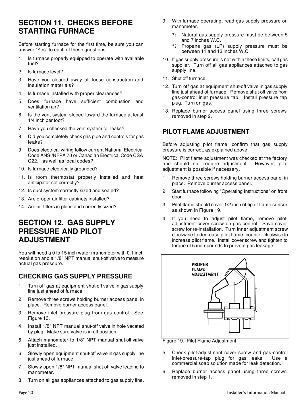
3.Pilot flame should cover 1/2 inch of tip of flame sensor as shown in Figure 19.
4.If you need to adjust pilot flame, remove pilot- adjustment cover screw on gas control. Save cover screw for
Figure 19. Pilot Flame Adjustment.
5.Check pilot-adjustment cover screw and gas -control
inlet-pressure-tap plug for gas leaks. Use a commercial soap solution made for leak detection.
6.Replace burner access panel using three screws removed in step 1.
Page 20 | Installer’s Information Manual |