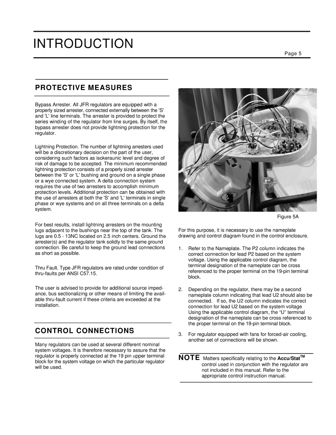
21-115532-001 specifications
The Siemens 21-115532-001 is an innovative device designed to enhance operational efficiency across various industrial applications. This equipment embodies the technology and reliability that Siemens is known for, making it a preferred choice among professionals in the field.One of the primary features of the Siemens 21-115532-001 is its advanced control capabilities. The device integrates seamlessly with existing industrial automation systems, enabling real-time monitoring and control. This allows users to adjust parameters dynamically and respond swiftly to changing operational conditions, ultimately leading to improved productivity and reduced downtime.
The device is equipped with robust communication technologies that facilitate data exchange with other industrial components. This includes compatibility with industry-standard protocols such as Profinet and EtherNet/IP, allowing for smooth integration into diverse ecosystems. The ability to connect with cloud-based systems enhances its functionality, providing valuable insights through data analytics.
In terms of physical characteristics, the Siemens 21-115532-001 is designed for durability. Housed in a rugged casing, it can withstand harsh industrial environments, ensuring longevity and reliability. It is waterproof and resistant to dust, making it suitable for use in outdoor settings or locations with challenging conditions.
The Siemens device also emphasizes safety features. It complies with international safety standards, ensuring that it can be safely integrated into various operations without compromising overall system integrity. This makes it an ideal choice for industries where safety is paramount.
Another significant aspect of the Siemens 21-115532-001 is its user-friendly interface. The device includes intuitive software that simplifies configuration and operation. Users can easily navigate through settings and features, reducing the learning curve and allowing for faster deployment in industrial applications.
In conclusion, the Siemens 21-115532-001 represents a combination of cutting-edge technology, robust design, and operational flexibility. Its advanced features and characteristics make it a vital asset for businesses looking to enhance their industrial processes. With its reliability and efficiency, it stands out as a leading choice in the market for industrial control solutions.

