Input Point Module (AFI5100)
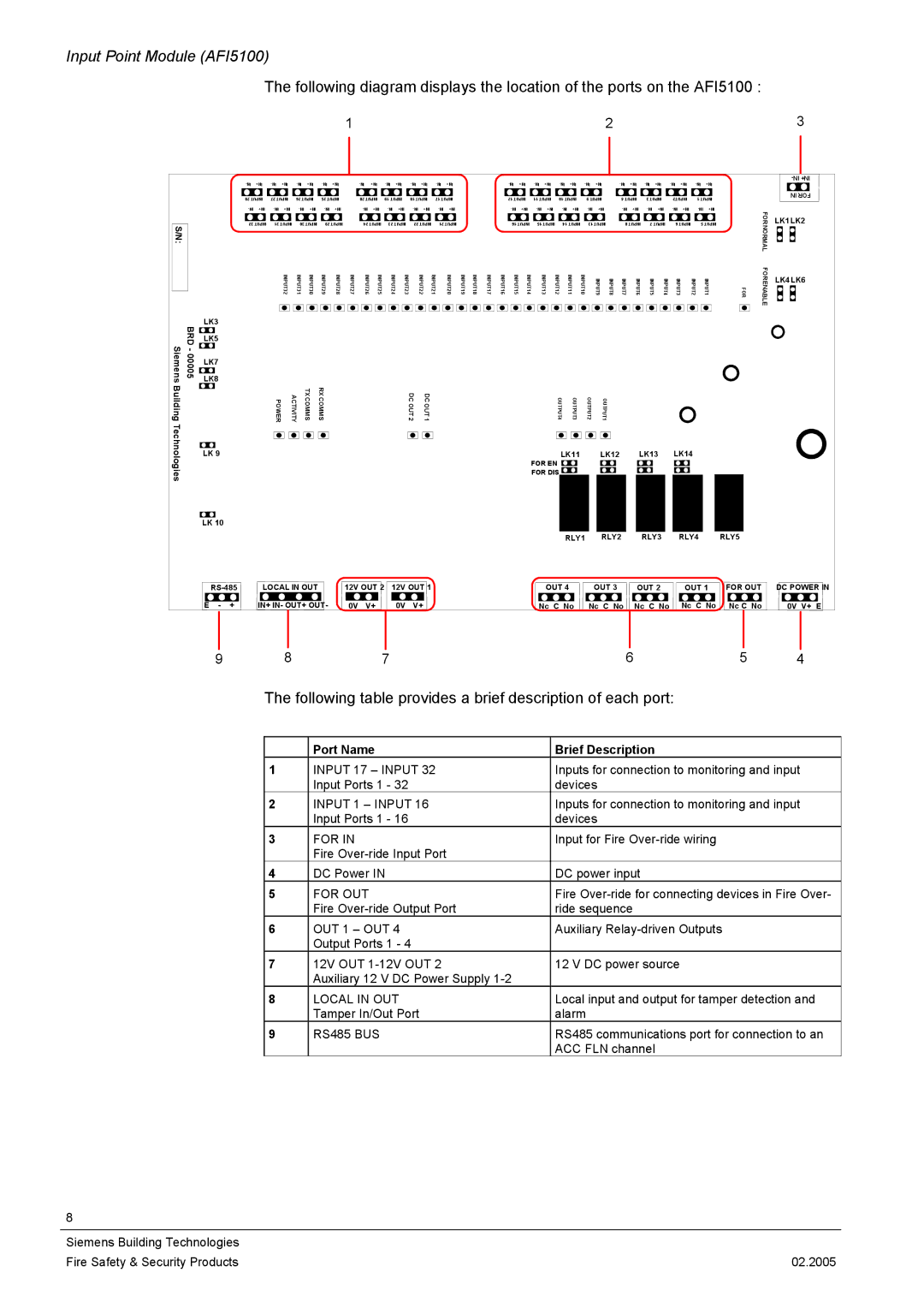
The following diagram displays the location of the ports on the AFI5100 :
|
|
|
|
|
|
|
|
|
|
| 1 |
|
|
|
|
|
|
|
|
|
|
|
|
|
|
|
|
|
| 2 |
|
|
|
|
|
|
|
|
|
| 3 | |
|
|
|
| +NI | +NI | +NI |
| +NI | +NI | +NI |
|
|
|
| +NI | +NI | +NI | +NI | +NI | +NI | +NI |
|
| |||||||||||||||||||
|
|
|
|
|
|
|
|
|
|
|
| |||||||||||||||||||||||||||||||
|
|
|
| 82 TUPNI | 72 TUPNI | 62 TUPNI | 52 TUPNI | 02 TUPNI | 91 TUPNI | 81 TUPNI | 71 TUPNI |
|
|
|
| 21 TUPNI | 11 TUPNI | 01 TUPNI | 9 TUPNI |
| 4 TUPNI | 3 TUPNI | 2TUPNI | 1 TUPNI |
|
| NI ROF | |||||||||||||||
|
|
|
| +NI | +NI | +NI | +NI | +NI | +NI | +NI |
|
|
|
| +NI | +NI | +NI |
| +NI | +NI | +NI |
| FOR |
| ||||||||||||||||||
S/N: |
|
|
| 23 TUPNI | 13 TUPNI | 03 TUPNI | 92 TUPNI | 42 TUPNI | 32 TUPNI | 22 TUPNI | 12 TUPNI |
|
|
|
| 61 TUPNI | 51 TUPNI | 41 TUPNI | 31 TUPNI |
| 8 TUPNI | 7 TUPNI |
| 6 TUPNI | 5 TUPNI |
| LK1LK2 | |||||||||||||||
|
|
|
|
|
|
|
|
|
|
|
|
|
|
|
|
|
|
|
|
|
|
|
|
|
|
|
|
|
|
|
|
|
|
|
|
|
|
|
| NORMAL |
| |
|
|
|
|
|
| I | I | I | I | I | I | I | I | I | I |
| I | I | I | I | I | I | I | I | I | I | I | I | I |
|
|
|
|
|
|
|
|
|
|
| FO | LK4LK6 |
|
|
|
|
|
| NPUT32 | NPUT31 | NPUT30 | NPUT29 | NPUT28 | NPUT27 | NPUT26 | NPUT25 | NPUT24 | NPUT23 |
| NPUT22 | NPUT21 | NPUT20 | NPUT19 | NPUT18 | NPUT17 | NPUT16 | NPUT15 | NPUT14 | NPUT13 | NPUT12 | NPUT11 | NPUT10 | INPUT9 | INPUT8 | INPUT7 | INPUT6 | INPUT5 | INPUT4 |
| INPUT3 | INPUT2 | INPUT1 |
| RENAB | |
|
|
|
|
|
|
|
| FOR |
| |||||||||||||||||||||||||||||||||
|
|
|
|
|
|
|
|
|
|
|
|
|
|
|
|
|
|
|
|
|
|
|
|
|
|
|
|
|
|
|
|
|
|
|
|
|
|
|
|
| LE |
|
| BRD | LK3 |
|
|
|
|
|
|
|
|
|
|
|
|
|
|
|
|
|
|
|
|
|
|
|
|
|
|
|
|
|
|
|
|
|
|
|
|
|
|
| |
| LK5 |
|
|
|
|
|
|
|
|
|
|
|
|
|
|
|
|
|
|
|
|
|
|
|
|
|
|
|
|
|
|
|
|
|
|
|
|
|
|
| ||
- S |
|
|
|
|
|
|
|
|
|
|
|
|
|
|
|
|
|
|
|
|
|
|
|
|
|
|
|
|
|
|
|
|
|
|
|
|
|
|
|
|
| |
iemens | 00005 | LK7 |
|
|
|
|
|
|
|
|
|
|
|
|
|
|
|
|
|
|
|
|
|
|
|
|
|
|
|
|
|
|
|
|
|
|
|
|
|
|
| |
LK8 |
|
|
|
|
|
|
|
|
|
|
|
|
|
|
|
|
|
|
|
|
|
|
|
|
|
|
|
|
|
|
|
|
|
|
|
|
|
|
| |||
Building |
|
|
|
|
| POWER | ACTIVITY | TXCOMMS | RXCOMMS |
|
|
|
|
| DCOUT2 | DCOUT1 |
|
|
|
|
|
|
|
|
| OUTPUT4 | OUTPUT3 | OUTPUT2 | OUTPUT1 |
|
|
|
|
|
|
|
|
|
|
|
| |
Techno |
| LK 9 |
|
|
|
|
|
|
|
|
|
|
|
|
|
|
|
|
|
|
|
|
|
|
| LK11 |
| LK12 |
| LK13 | LK14 |
|
|
|
| |||||||
logies |
|
|
|
|
|
|
|
|
|
|
|
|
|
|
|
|
|
|
|
|
|
|
|
|
| FOR EN |
|
|
|
|
|
|
|
|
|
|
|
|
|
|
| |
|
|
|
|
|
|
|
|
|
|
|
|
|
|
|
|
|
|
|
|
|
|
|
|
| FOR DIS |
|
|
|
|
|
|
|
|
|
|
|
|
|
|
| ||
|
|
|
|
|
|
|
|
|
|
|
|
|
|
|
|
|
|
|
|
|
|
|
|
|
|
|
|
|
|
|
|
|
|
|
|
|
|
|
|
|
| |
|
| LK 10 |
|
|
|
|
|
|
|
|
|
|
|
|
|
|
|
|
|
|
|
|
|
|
|
|
|
|
|
|
|
|
|
|
|
|
|
|
|
|
| |
|
|
|
|
|
|
|
|
|
|
|
|
|
|
|
|
|
|
|
|
|
|
|
|
|
|
| RLY1 | RLY2 |
|
| RLY3 |
| RLY4 |
| RLY5 |
|
| |||||
|
|
| LOCAL IN OUT |
|
| 12V OUT 2 | 12V OUT 1 |
|
|
|
|
|
|
|
| OUT 4 |
| OUT 3 |
| OUT 2 |
| OUT 1 | FOR OUT |
| DC POWER IN | |||||||||||||||||
|
| E | - | + | IN+ IN- OUT+ OUT- |
| 0V | V+ |
| 0V | V+ |
|
|
|
|
|
|
|
| Nc C No | Nc C No | Nc C No |
| Nc C No | Nc C No |
| 0V V+ E | |||||||||||||||
|
|
| 9 |
|
| 8 |
|
|
|
|
| 7 |
|
|
|
|
|
|
|
|
|
|
|
|
|
|
|
|
| 6 |
|
|
|
|
|
| 5 |
| 4 | |||
The following table provides a brief description of each port:
| Port Name | Brief Description |
1 | INPUT 17 – INPUT 32 | Inputs for connection to monitoring and input |
| Input Ports 1 - 32 | devices |
2 | INPUT 1 – INPUT 16 | Inputs for connection to monitoring and input |
| Input Ports 1 - 16 | devices |
3 | FOR IN | Input for Fire |
| Fire |
|
4 | DC Power IN | DC power input |
5 | FOR OUT | Fire |
| Fire | ride sequence |
6 | OUT 1 – OUT 4 | Auxiliary |
| Output Ports 1 - 4 |
|
7 | 12V OUT | 12 V DC power source |
| Auxiliary 12 V DC Power Supply |
|
8 | LOCAL IN OUT | Local input and output for tamper detection and |
| Tamper In/Out Port | alarm |
9 | RS485 BUS | RS485 communications port for connection to an |
|
| ACC FLN channel |
8
Siemens Building Technologies |
|
Fire Safety & Security Products | 02.2005 |