Input Point Module (AFI5100)
1.7Links and Jumpers
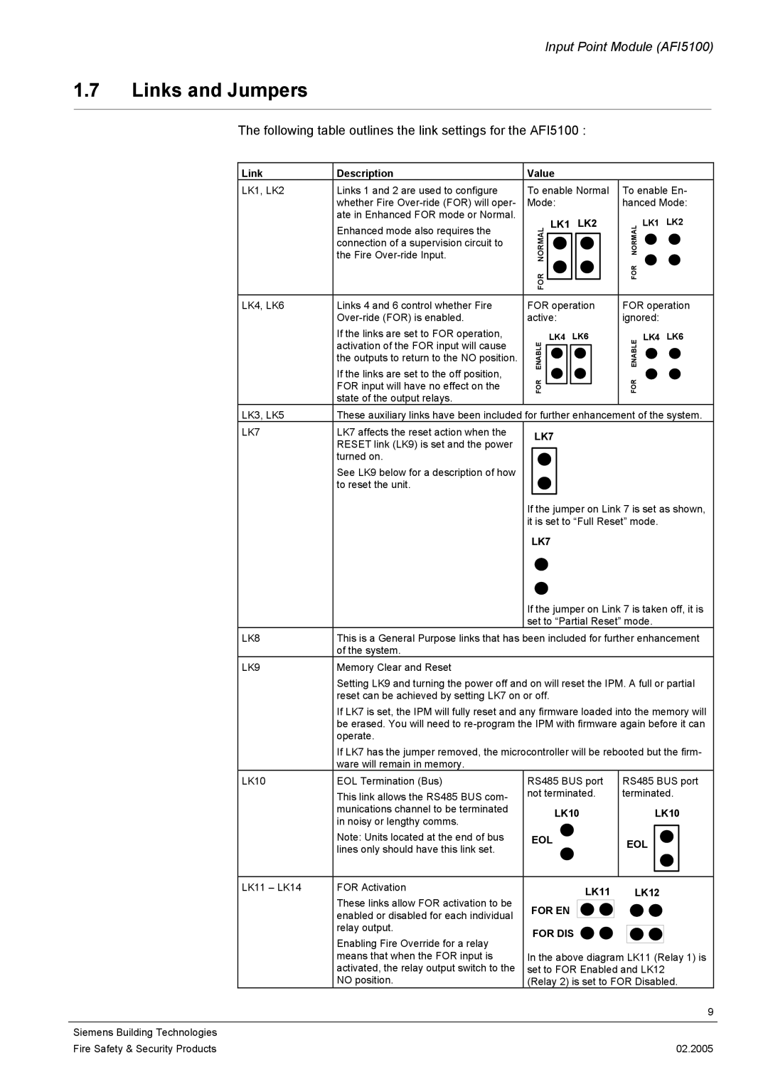
The following table outlines the link settings for the AFI5100 :
Link | Description | Value |
|
| |
LK1, LK2 | Links 1 and 2 are used to configure | To enable Normal | To enable En- | ||
| whether Fire | Mode: |
| hanced Mode: | |
| ate in Enhanced FOR mode or Normal. |
| LK1 | LK2 | LK1 LK2 |
| Enhanced mode also requires the |
| |||
| AMORL |
|
| LAMR ON | |
| connection of a supervision circuit to |
|
| ||
| the Fire | N |
|
|
|
|
| OR |
|
| ROF |
|
| F |
|
|
|
LK4, LK6 | Links 4 and 6 control whether Fire | FOR operation | FOR operation | ||
| active: |
| ignored: | ||
| If the links are set to FOR operation, |
| LK4 | LK6 | LK4 LK6 |
| activation of the FOR input will cause | ELB ANE |
|
| ELBA NE |
| the outputs to return to the NO position. |
|
| ||
| If the links are set to the off position, | ROF |
|
| ROF |
| FOR input will have no effect on the |
|
| ||
| state of the output relays. |
|
|
|
|
LK3, LK5 | These auxiliary links have been included for further enhancement of the system. | ||||
LK7 | LK7 affects the reset action when the | LK7 |
|
| |
| RESET link (LK9) is set and the power |
|
| ||
|
|
|
|
| |
| turned on. |
|
|
|
|
| See LK9 below for a description of how |
|
|
|
|
| to reset the unit. |
|
|
|
|
|
| If the jumper on Link 7 is set as shown, | |||
|
| it is set to “Full Reset” mode. | |||
LK7
|
| If the jumper on Link 7 is taken off, it is | |
|
| set to “Partial Reset” mode. | |
LK8 | This is a General Purpose links that has been included for further enhancement | ||
| of the system. |
|
|
LK9 | Memory Clear and Reset |
|
|
| Setting LK9 and turning the power off and on will reset the IPM. A full or partial | ||
| reset can be achieved by setting LK7 on or off. |
| |
| If LK7 is set, the IPM will fully reset and any firmware loaded into the memory will | ||
| be erased. You will need to | ||
| operate. |
|
|
| If LK7 has the jumper removed, the microcontroller will be rebooted but the firm- | ||
| ware will remain in memory. |
|
|
LK10 | EOL Termination (Bus) | RS485 BUS port | RS485 BUS port |
| This link allows the RS485 BUS com- | not terminated. | terminated. |
| munications channel to be terminated | LK10 | LK10 |
| in noisy or lengthy comms. | ||
|
|
| |
| Note: Units located at the end of bus | EOL | EOL |
| lines only should have this link set. |
| |
|
|
| |
LK11 – LK14 | FOR Activation | LK11 | LK12 |
| These links allow FOR activation to be | ||
| FOR EN |
| |
| enabled or disabled for each individual |
| |
|
|
| |
| relay output. | FOR DIS |
|
| Enabling Fire Override for a relay |
| |
|
|
| |
| means that when the FOR input is | In the above diagram LK11 (Relay 1) is | |
| activated, the relay output switch to the | set to FOR Enabled and LK12 | |
| NO position. | (Relay 2) is set to FOR Disabled. | |
|
|
| 9 |
Siemens Building Technologies |
|
|
|
Fire Safety & Security Products |
|
| 02.2005 |