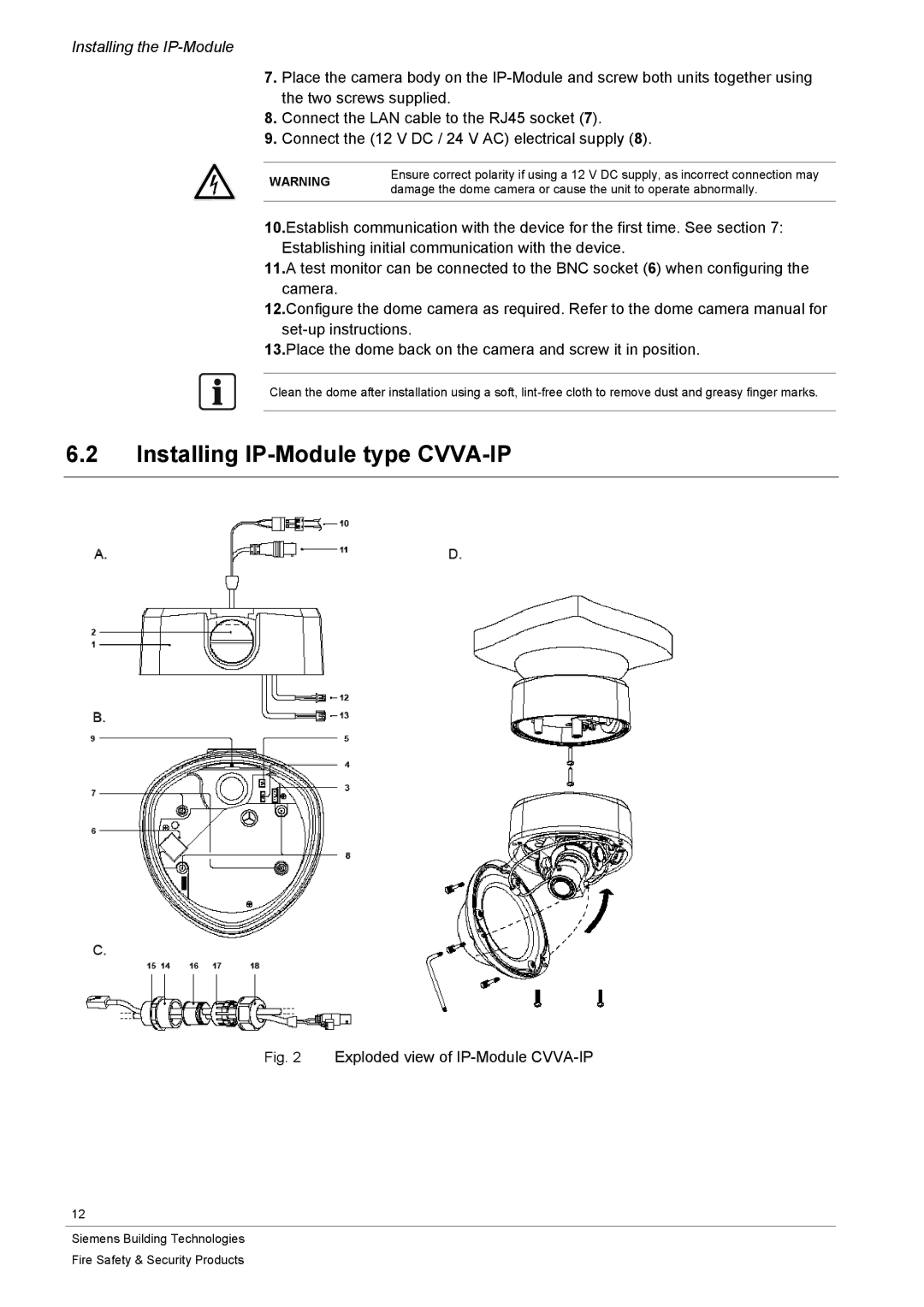
CFVA-IP specifications
Siemens CFVA-IP is an advanced control system designed for industrial automation, combining performance, flexibility, and reliability to meet the diverse demands of modern manufacturing processes. This system is engineered to operate seamlessly across various industries, including automotive, food and beverage, and pharmaceuticals.One of the primary features of the CFVA-IP is its integration capability with existing infrastructure. It supports a wide array of communication protocols, allowing for easy connection with legacy systems and new components alike. This ensures a smooth transition and interoperability within the industrial ecosystem, reducing downtime and enhancing productivity.
The CFVA-IP utilizes state-of-the-art technologies, such as Ethernet and IP-based communication, to facilitate high-speed data transfer and real-time control. This enables operators to monitor processes and make informed decisions quickly. The system is equipped with advanced diagnostic tools that provide insights into operational performance, helping to identify potential issues before they escalate into significant problems.
A notable characteristic of the Siemens CFVA-IP is its modular design. This allows for easy customization and scalability, enabling manufacturers to expand their systems as needed without significant overhauls. Users can select from various input/output modules, communication interfaces, and power supplies to tailor the system to their specific applications and requirements.
Additionally, the CFVA-IP features comprehensive safety measures, including built-in redundancy and support for safety protocols. It complies with international safety standards, ensuring that operations can continue securely even in critical scenarios. This feature is particularly essential in industries where safety and regulatory compliance are paramount.
Another significant advantage of the Siemens CFVA-IP is its user-friendly interface. The system includes intuitive software tools designed to ease programming and control. The graphical interface simplifies configuration and monitoring, allowing even less technically inclined users to operate the system efficiently. Moreover, training tools and extensive documentation are available, ensuring that staff can quickly adapt to the new system.
In conclusion, Siemens CFVA-IP stands out as a versatile and robust solution for industrial automation. Its combination of integration capability, advanced technologies, modular design, safety features, and user-friendly interface makes it an ideal choice for companies looking to modernize their manufacturing processes while maintaining efficiency and reliability. The CFVA-IP not only meets current automation needs but is also poised to adapt to future challenges in the ever-evolving industrial landscape.

