english
3.2Pinout
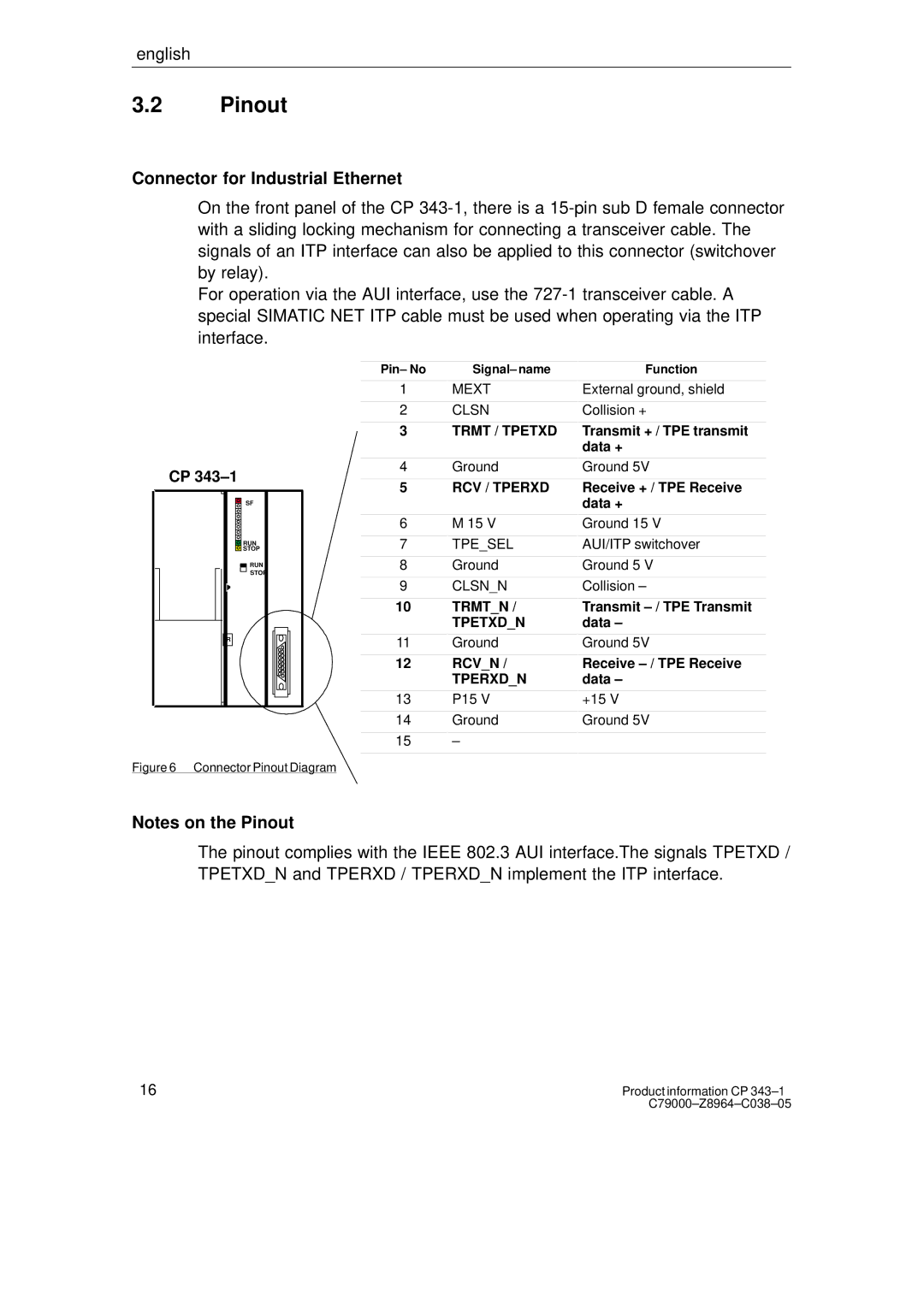
Connector for Industrial Ethernet
On the front panel of the CP
For operation via the AUI interface, use the
CP
SF
RUN |
STOP |
RUN
STOP
R
Figure 6 Connector Pinout Diagram
Pin– No
1
2
3
4
5
6
7
8
9
10
11
12
13
14
15
Signal– name
MEXT
CLSN
TRMT / TPETXD
Ground
RCV / TPERXD
M 15 V
TPE_SEL
Ground
CLSN_N
TRMT_N /
TPETXD_N
Ground
RCV_N /
TPERXD_N
P15 V
Ground
–
Function
External ground, shield
Collision +
Transmit + / TPE transmit data +
Ground 5V
Receive + / TPE Receive data +
Ground 15 V
AUI/ITP switchover
Ground 5 V
Collision –
Transmit
Ground 5V
Receive
+15 V
Ground 5V
Notes on the Pinout
The pinout complies with the IEEE 802.3 AUI interface.The signals TPETXD / TPETXD_N and TPERXD / TPERXD_N implement the ITP interface.
16Product information CP