3 Operating the SAMMS-LV Device
3.19 Stator Protection
By selecting the overload class slightly greater than or equal to the motor’s starting time, the motor model defines an energy I2t value. In this value, I equals 600% of the motor’s full load current and t equals the overload class selected.
If the amount of energy exerted by the motor during start, stall or under locked rotor condition exceeds the amount of energy defined by the overload class selected, the
3.20 Repetitive Starts
The motor model allows repetitive starts without nuisance tripping while protecting the motor against overload and stall conditions. Repetitive starts can occur as long as the following conditions are met:
1.The energy exerted by the motor during start does not exceed the energy defined by the overload class selected.
2.The motor winding temperature does not exceed the maxi- mum temperature allowed.
3.The
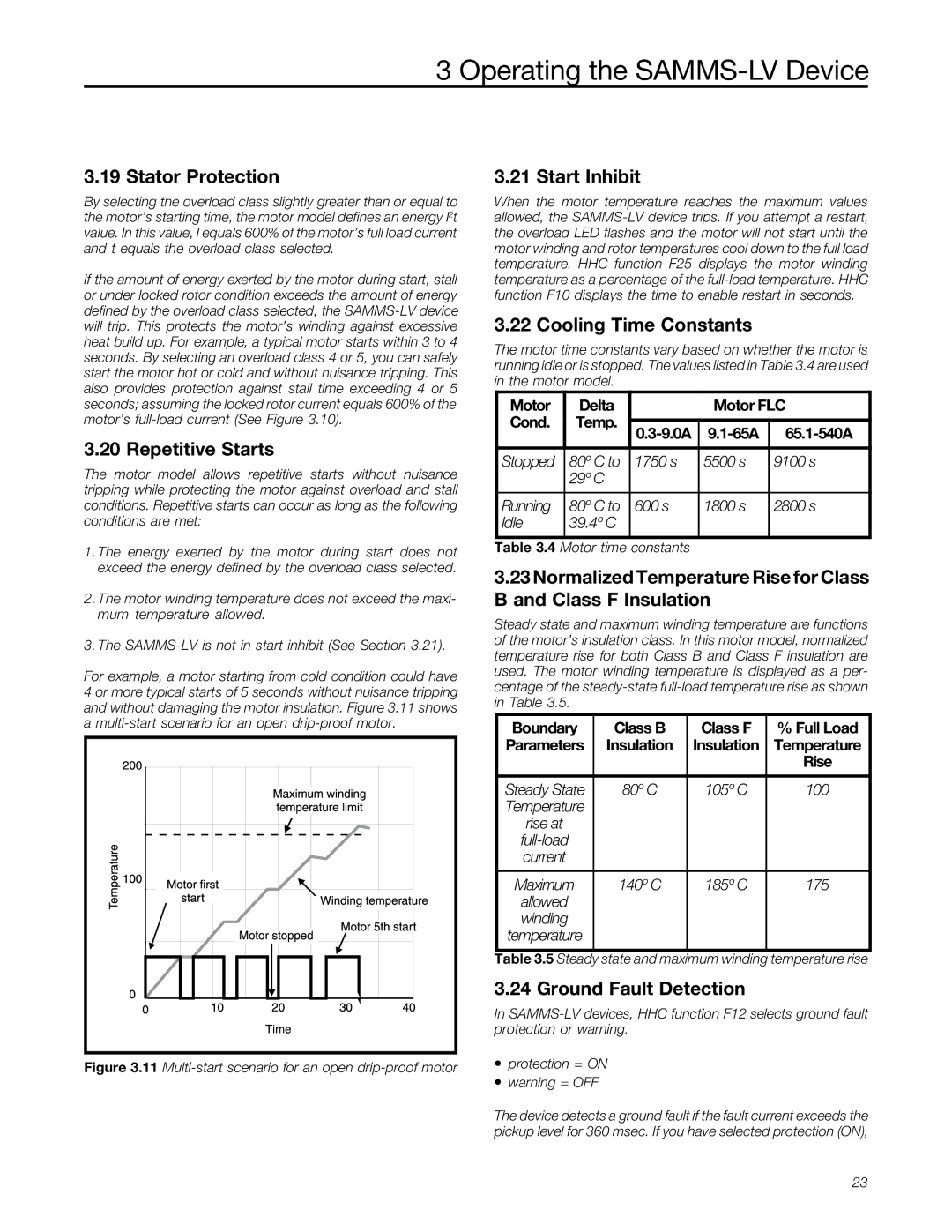
For example, a motor starting from cold condition could have 4 or more typical starts of 5 seconds without nuisance tripping and without damaging the motor insulation. Figure 3.11 shows a
Figure 3.11 Multi-start scenario for an open drip-proof motor
3.21 Start Inhibit
When the motor temperature reaches the maximum values allowed, the
3.22 Cooling Time Constants
The motor time constants vary based on whether the motor is running idle or is stopped. The values listed in Table 3.4 are used in the motor model.
Motor | Delta |
| Motor FLC | ||
Cond. | Temp. |
|
|
| |
|
| ||||
|
|
|
|
| |
Stopped | 80º C to | 1750 s | 5500 s | 9100 s | |
| 29º C |
|
|
| |
|
|
|
|
| |
Running | 80º C to | 600 s | 1800 s | 2800 s | |
Idle | 39.4º C |
|
|
| |
Table 3.4 Motor time constants
3.23Normalized Temperature Rise for Class B and Class F Insulation
Steady state and maximum winding temperature are functions of the motor’s insulation class. In this motor model, normalized temperature rise for both Class B and Class F insulation are used. The motor winding temperature is displayed as a per- centage of the
Boundary | Class B | Class F | % Full Load |
Parameters | Insulation | Insulation | Temperature |
|
|
| Rise |
|
|
|
|
Steady State | 80º C | 105º C | 100 |
Temperature |
|
|
|
rise at |
|
|
|
|
|
| |
current |
|
|
|
|
|
|
|
Maximum | 140º C | 185º C | 175 |
allowed |
|
|
|
winding |
|
|
|
temperature |
|
|
|
Table 3.5 Steady state and maximum winding temperature rise
3.24 Ground Fault Detection
In
∙protection = ON
∙warning = OFF
The device detects a ground fault if the fault current exceeds the pickup level for 360 msec. If you have selected protection (ON),
23