3 Operating the SAMMS-LV Device
Function | Function Description | Range | Step Size | |
Number |
|
|
|
|
F0 | Select ambient temperature. | 0 - 70º C | 5º C | |
|
|
|
| |
F1 | Display (or change for | 0 - 9999 | 1 | |
| the control circuit number, |
|
|
|
| Enable/disable incomplete sequence |
|
|
|
| status. |
|
|
|
|
|
|
| |
F2 | Display the size for | 1A, 1B, 1C, 2A, 2B, 3, | As shown | |
| controller, or the | 4, 5, 6 |
| |
|
|
|
| |
|
|
|
| |
F3 | Display the | 1A, 1B, 1C, 2A, 2B, 3, | As shown | |
| 4, 5, 6, OFF |
| ||
|
|
|
| |
F4 | Select the | 1A: | 0.3 - 1.5A | 0.1A |
| for the size for | 1B: | 1.2 - 6A | 0.1A |
| controller or the | 1C: | 4.8 - 24A | 0.1A |
| 2A: | 10 - 36A | 1A | |
|
| 2B: | 10 - 45A | 1A |
|
| 3: | 20 - 90A | 1A |
|
| 4: | 40 - 135A | 1A |
|
| 5: | 80 - 270A | 1A |
|
| 6: | 160 - 540A | 2A |
F4A | Display the primary current if 5A | Function of size in F2 | Function of size in F2 | |
| secondary CT's are used. |
|
|
|
|
|
|
|
|
F5 | Select the | 1A: | 0.3 - 1.5A | 0.1A |
| for the | 1B: | 1.2 - 6A | 0.1A |
| motor controllers. F5 is OFF for single | 1C: | 4.8 - 24A | 0.1A |
| speed motor controllers. | 2A: | 10 - 36A | 1A |
|
| 2B: | 10 - 45A | 1A |
|
| 3: | 20 - 90A | 1A |
|
| 4: | 40 - 135A | 1A |
|
| 5: | 80 - 270A | 1A |
|
| 6: | 160 - 540A | 2A |
|
|
|
| |
F5A | Display the primary current if 5A | Function of size in F3 | Function of size in F3 | |
| secondary CT's are used. |
|
|
|
|
|
|
| |
F6 | Select the service factor. | 1 or 1.15 | N/A | |
|
|
|
|
|
F7 | Select the overload trip class. |
| 1 | |
|
|
|
| |
F8 | Enable/disable autoreset of overload | ON/OFF | N/A | |
| and external trips. |
|
|
|
|
|
|
| |
F9 | Enable/disable phase unbalance | ON/OFF | N/A | |
| protection. |
|
|
|
|
|
|
| |
F10 | Display the time to wait until the motor | Real Time Value | 1s | |
| can be restarted. Applies after an |
|
|
|
| overload trip with the winding or |
|
|
|
| housing temperature above the |
|
|
|
| maximum allowed for restarting. |
|
|
|
F11 | Enable/disable the emergency restart | ON/OFF | N/A | |
| capability. |
|
|
|
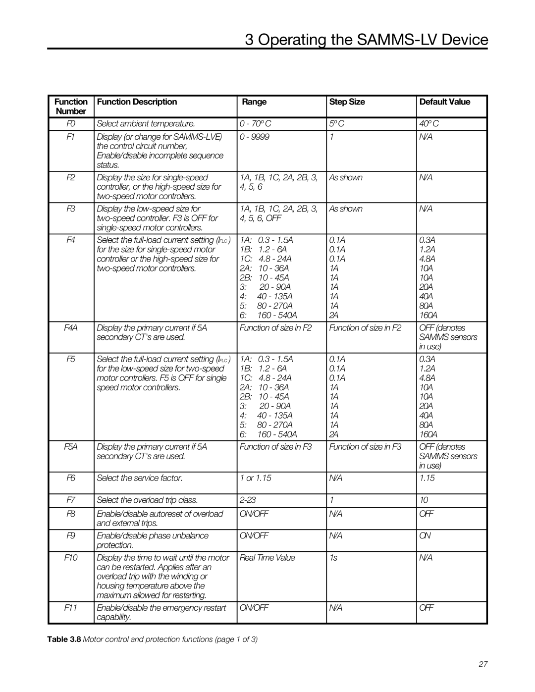
Table 3.8 Motor control and protection functions (page 1 of 3)
Default Value
40º C
N/A
N/A
N/A
0.3A
1.2A
4.8A
10A
10A
20A
40A
80A
160A
OFF (denotes SAMMS sensors in use)
0.3A
1.2A
4.8A
10A
10A
20A
40A
80A
160A
OFF (denotes SAMMS sensors in use)
1.15
10 OFF
ON
N/A
OFF
27
