Multiplexer User's Guide
Confidential / Released
s
mobile
RTS/CTS on the logical channels
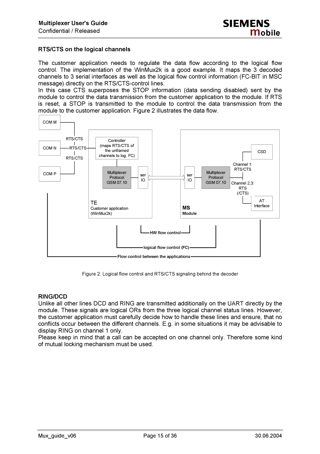
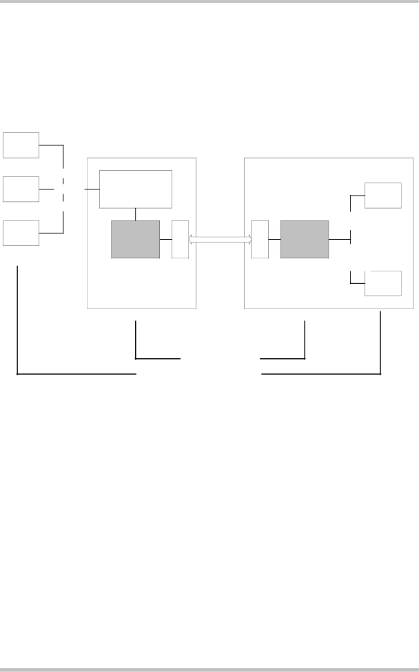
The customer application needs to regulate the data flow according to the logical flow control. The implementation of the WinMux2k is a good example. It maps the 3 decoded channels to 3 serial interfaces as well as the logical flow control information
In this case CTS superposes the STOP information (data sending disabled) sent by the module to control the data transmission from the customer application to the module. If RTS is reset, a STOP is transmitted to the module to control the data transmission from the module to the customer application. Figure 2 illustrates the data flow.
COM M
COM N
COM P
RTS/CTS
RTS/CTS
RTS/CTS
Controller |
| |
(maps RTS/CTS of |
| |
the unframed |
| |
channels to log. FC) |
| |
Multiplexer | ser | |
Protocol | ||
IO | ||
GSM 07.10 | ||
| ||
TE |
| |
Customer application |
| |
(WinMux2k) |
|
|
| CSD | |
|
| Channel 1: | |
| Multiplexer | RTS/CTS | |
ser |
| ||
Protocol |
| ||
IO |
| ||
GSM 07.10 | Channel 2,3: | ||
| |||
|
| RTS | |
|
| (/CTS) | |
|
| AT | |
MS |
| Interface | |
Module |
|
|
![]() HW flow control
HW flow control![]()
logical flow control (FC) Flow control between the applications
Figure 2: Logical flow control and RTS/CTS signaling behind the decoder
RING/DCD
Unlike all other lines DCD and RING are transmitted additionally on the UART directly by the module. These signals are logical ORs from the three logical channel status lines. However, the customer application must carefully decide how to handle these lines and ensure, that no conflicts occur between the different channels. E.g. in some situations it may be advisable to display RING on channel 1 only.
Please keep in mind that a call can be accepted on one channel only. Therefore some kind of mutual locking mechanism must be used.
Mux_guide_v06 | Page 15 of 36 | 30.06.2004 |