6.CERTIFICATIONS AND COMPLIANCES:
SAFETY
IEC
ELECTROMAGNETIC COMPATIBILITY
Immunity to EN |
|
|
|
Electrostatic discharge | EN | ||
|
| Level 3; 8 | Kv air |
Electromagnetic RF fields | EN | Level 3; 10 V/m | |
|
| 80 MHz - 1 GHz | |
Fast transients (burst) | EN | Level 4; 2 | Kv I/O |
|
| Level 3; 2 | Kv power |
RF conducted interference | EN | Level 3; 10 V/rms 1 | |
|
| 150 KHz - 80 MHz | |
Emissions to EN |
|
|
|
RF interference | EN 55011 Enclosure class A | ||
|
| Power mains class A | |
Note:
1.
Install 1 ferrite core RLC #FCOR0000 or equivalent, to power cable at unit. I/O cables are routed in metal conduit connected to earth ground.
7.FIELD CONNECTIONS: Removable screw terminal blocks.
8.WEIGHT: 1.25 lb (0.58 kg)
STATUS LED’s
Three LED’s provide status indication and are described in Table 1. The
Table 1
Paradigm PROFIBUS Host Adapter Status LED Description
NAME | COLOR | FUNCTION | |
|
|
| |
DATA | Red | ||
(driven by SPC3 DATA_EX pin) | |||
|
| ||
|
|
| |
WD | Green | Watchdog State Machine State | |
|
|
| |
DP | Red | DP Control State Machine State | |
|
|
|
Table 2
Led Indication of Paradigm PROFIBUS Host Adapter State
In
DATA LED | WD LED | DP LED | PARADIGM PROFIBUS HOST ADAPTER STATE | |
(Red) | (Green) | (Red) | ||
| ||||
|
|
|
| |
OFF | ON | OFF | Baud Search state | |
|
|
|
| |
OFF | FLASHING | OFF | Baud Control State | |
|
|
|
| |
OFF | OFF | ON | Waiting for Parameterization Telegram | |
|
|
|
| |
OFF | OFF | FLASHING | Waiting for Configuration Telegram | |
|
|
|
| |
ON | OFF | OFF | Data Exchange State | |
|
|
|
|
WIRING AND CONNECTIONS
POWER SUPPLY REQUIREMENTS
The Operator Interface requires an 11 to 30 VDC power supply rated at
2.25W unless otherwise stated on the label.
!The terminal may take as little as 100 mA in certain circumstances, so be sure that the chosen power supply can operate correctly with this load. Large
In any case, it is very important that the power supply is mounted correctly if the unit is to operate reliably. A very high proportion of reported problems are caused by incorrect power supply installation, so please take care to observe the following points...
!The power supply must be mounted close to the unit, with usually not more than 6 feet of cable between the supply and the PAPBH. Ideally, as short a length as is possible should be used.
!The wire used to connect the PAPBH’s power supply should be of at least 22 gauge wire. If a longer cable run is used, you should use a heavier gauge wire. The routing of the cable should be kept away from large contactors, inverters and other devices which may generate significant electrical noise.
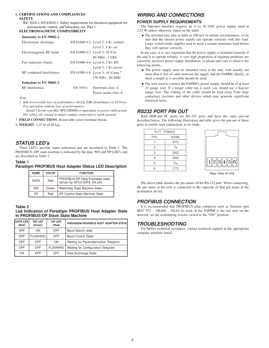
RS232 PORT PIN OUT
Both HMI and PC ports are
Rear View of Unit
The above table denotes the pin names of the
PROFIBUS CONNECTION
It is recommended that PROFIBUS plug connector such as Siemens part 6ES7 972 – 0BA00 – 0XA0 be used. If the PAPBH is the last unit on the network, set the terminating resistor switch to the “ON” position.
TROUBLESHOOTING
For further technical assistance, contact technical support at the appropriate company numbers listed.
2