3Installing and wiring the hardware
Warning
Dangerous electrical voltages!
Death or serious bodily injury and damage to machinery and equipment can occur if you do not observe the follow- ing safety precautions.
Before starting work, discon- nect the system and the device from the power supply.
18
3.3 Wiring the components
Wire the system components to the CPU 312C. This enables the CPU 312C to detect and evaluate the state of the components with the help of the control pro- gram.
•The
•The motor is the signal receiver. You connect the signal receiver to the output terminals of the CPU 312C. The output terminals are labeled with “DO”.
The entire control loop is connected to the power supply via the CPU 312C.
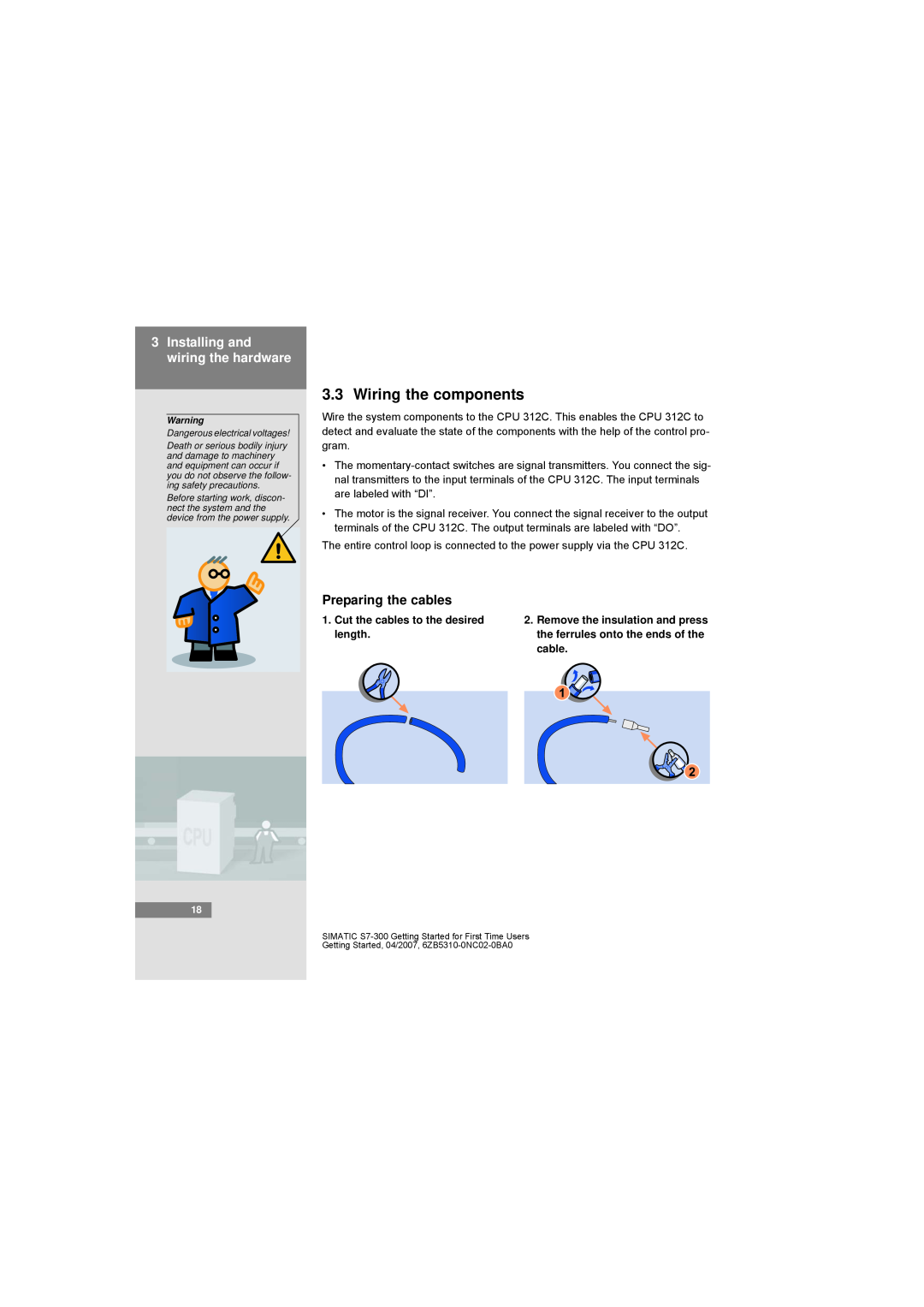
Preparing the cables
1. Cut the cables to the desired | 2. Remove the insulation and press | |
length. |
| the ferrules onto the ends of the |
|
| cable. |
|
|
|
|
|
|
SIMATIC