VCAUTION
CONDUCTING DIELECTRIC AND/OR
Do not perform dielectric or high potential
tests with the TPS3 unit installed.
V DANGER
Hazardous voltage.
Will cause death or serious injury.
Keep Out.
Qualified personnel only.
Disconnect and lock off all power before working on this equipment.
TPS3 12 and TPS3 15 Installation Instructions
•Meet all National and Local codes (NEC® Article 285 addresses SPDs)
•Mount SPD as close to panel or equipment as possible to keep leads short
•Ensure leads are as short and straight as possible, including neutral and ground. Consider a breaker position that is closest to the SPD and the panel’s neutral & ground
•Suggested breaker & conductor size is
•Make sure system is grounded per NEC® and clear of faults before energizing SPD.
Certain options or implementations require extra consideration. See appropriate sections within this manual:
•Line Side Installation (page 4)
•Disconnect Switch Option (page 9)
•Flush Mount Option (page 9)
•
•NEMA 3R drain holes (page 7)
Use a voltmeter to check all voltages to ensure correct SPD
If SPD has Dry Contact, Remote Monitoring or Remote Display,
Remove power for panel. Confirm panel is deenergized.
Identify connection/breaker location and SPD location.
Make sure leads are short. Reducing inches matters.
InstallationTips: SPD moduleis mountedon backplanewithin its enclosure. In many cases, the backplane assembly can be unbolted and rotated in two or four directions to yield shortest leads. See Figure 7. Carefully disconnect ribbon cable(s) and unbolt backplane assembly. Various configurations have limited work space. Please be patient. Installation may be easier if disconnect switch is temporarily removed from DIN- rail, or module/backplane is temporarily removed.
Remove an appropriately sized knockout from panel. Create an appropriately sized and located hole in the SPD enclosure.
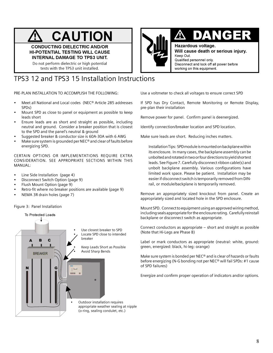
Figure 3: Panel Installation
To Protected Loads
A B C
BREAKER
•Use closest breaker to SPD
•Locate SPD close to intended breaker
•Keep Leads Short as Possible
•Avoid Sharp Bends
Mount SPD. Connect to equipment using an approved wiring method, including seals appropriate for the enclosure rating. Carefully reinstall backplane or disconnect switch as appropriate.
Connect conductors as appropriate – short and straight as possible (Note that
Label or mark conductors as appropriate (neutral: white, ground:
green, energized: black,
Make sure system is bonded per NEC® and is clear of hazards or faults before energizing
N | G |
•Outdoor installation requires appropriate weather sealing at nipple
of SPD failures)
Energize and confirm proper operation of indicators and/or options.
8