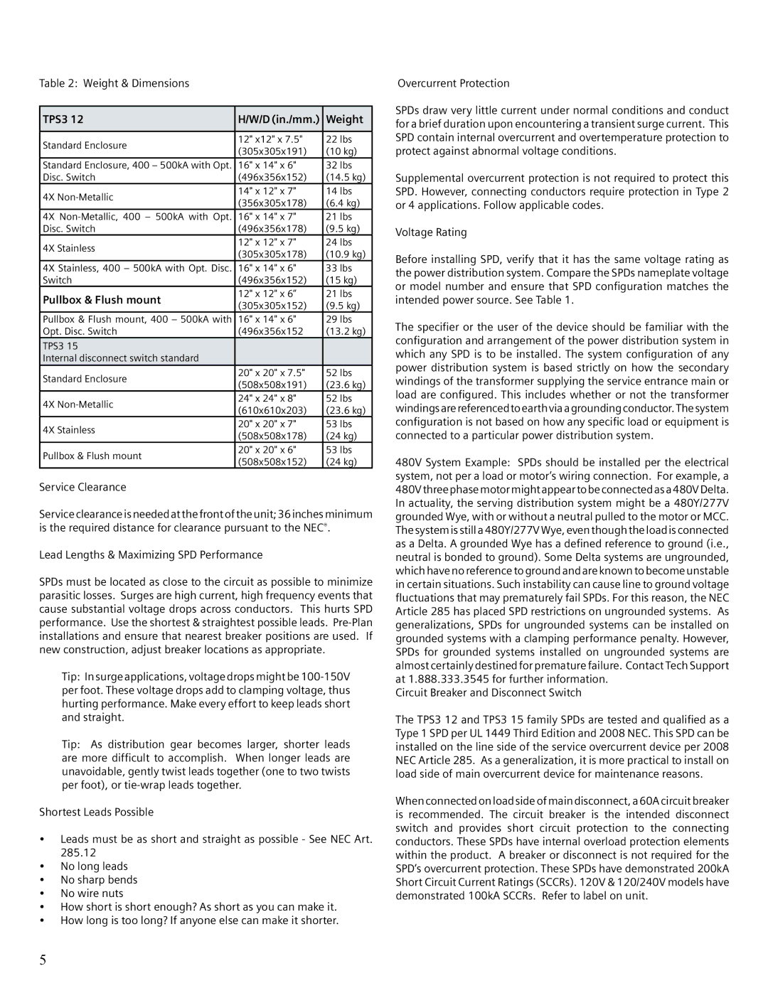
Table 2: Weight & Dimensions
TPS3 12 | H/W/D (in./mm.) | Weight | |
|
|
| |
Standard Enclosure | 12" x12" x 7.5" | 22 lbs | |
(305x305x191) | (10 kg) | ||
| |||
Standard Enclosure, 400 – 500kA with Opt. | 16" x 14" x 6" | 32 lbs | |
Disc. Switch | (496x356x152) | (14.5 kg) | |
4X | 14" x 12" x 7" | 14 lbs | |
(356x305x178) | (6.4 kg) | ||
| |||
4X | 16" x 14" x 7" | 21 lbs | |
Disc. Switch | (496x356x178) | (9.5 kg) | |
4X Stainless | 12" x 12" x 7" | 24 lbs | |
(305x305x178) | (10.9 kg) | ||
| |||
4X Stainless, 400 – 500kA with Opt. Disc. | 16" x 14" x 6" | 33 lbs | |
Switch | (496x356x152) | (15 kg) | |
Pullbox & Flush mount | 12" x 12" x 6” | 21 lbs | |
(305x305x152) | (9.5 kg) | ||
| |||
Pullbox & Flush mount, 400 – 500kA with | 16" x 14" x 6" | 29 lbs | |
Opt. Disc. Switch | (496x356x152 | (13.2 kg) | |
TPS3 15 |
|
| |
Internal disconnect switch standard |
|
| |
Standard Enclosure | 20" x 20" x 7.5" | 52 lbs | |
(508x508x191) | (23.6 kg) | ||
| |||
4X | 24" x 24" x 8" | 52 lbs | |
(610x610x203) | (23.6 kg) | ||
| |||
4X Stainless | 20" x 20" x 7" | 53 lbs | |
(508x508x178) | (24 kg) | ||
| |||
Pullbox & Flush mount | 20" x 20" x 6" | 53 lbs | |
(508x508x152) | (24 kg) | ||
|
Service Clearance
Service clearance is needed at the front of the unit; 36 inches minimum is the required distance for clearance pursuant to the NEC®.
Lead Lengths & Maximizing SPD Performance
SPDs must be located as close to the circuit as possible to minimize parasitic losses. Surges are high current, high frequency events that cause substantial voltage drops across conductors. This hurts SPD performance. Use the shortest & straightest possible leads.
Tip: In surge applications, voltage drops might be
Tip: As distribution gear becomes larger, shorter leads are more difficult to accomplish. When longer leads are unavoidable, gently twist leads together (one to two twists per foot), or
Shortest Leads Possible
•Leads must be as short and straight as possible - See NEC Art. 285.12
•No long leads
•No sharp bends
•No wire nuts
•How short is short enough? As short as you can make it.
•How long is too long? If anyone else can make it shorter.
Overcurrent Protection
SPDs draw very little current under normal conditions and conduct for a brief duration upon encountering a transient surge current. This SPD contain internal overcurrent and overtemperature protection to protect against abnormal voltage conditions.
Supplemental overcurrent protection is not required to protect this SPD. However, connecting conductors require protection in Type 2 or 4 applications. Follow applicable codes.
Voltage Rating
Before installing SPD, verify that it has the same voltage rating as the power distribution system. Compare the SPDs nameplate voltage or model number and ensure that SPD configuration matches the intended power source. See Table 1.
The specifier or the user of the device should be familiar with the configuration and arrangement of the power distribution system in which any SPD is to be installed. The system configuration of any power distribution system is based strictly on how the secondary windings of the transformer supplying the service entrance main or load are configured. This includes whether or not the transformer windingsarereferencedtoearthvia a groundingconductor.Thesystem configuration is not based on how any specific load or equipment is connected to a particular power distribution system.
480V System Example: SPDs should be installed per the electrical system, not per a load or motor’s wiring connection. For example, a 480V three phase motor might appear to be connected as a 480V Delta. In actuality, the serving distribution system might be a 480Y/277V grounded Wye, with or without a neutral pulled to the motor or MCC. The system is still a 480Y/277V Wye, even though the load is connected as a Delta. A grounded Wye has a defined reference to ground (i.e., neutral is bonded to ground). Some Delta systems are ungrounded, which have no reference to ground and are known to become unstable in certain situations. Such instability can cause line to ground voltage fluctuations that may prematurely fail SPDs. For this reason, the NEC Article 285 has placed SPD restrictions on ungrounded systems. As generalizations, SPDs for ungrounded systems can be installed on grounded systems with a clamping performance penalty. However, SPDs for grounded systems installed on ungrounded systems are almost certainly destined for premature failure. Contact Tech Support at 1.888.333.3545 for further information.
Circuit Breaker and Disconnect Switch
The TPS3 12 and TPS3 15 family SPDs are tested and qualified as a Type 1 SPD per UL 1449 Third Edition and 2008 NEC. This SPD can be installed on the line side of the service overcurrent device per 2008 NEC Article 285. As a generalization, it is more practical to install on load side of main overcurrent device for maintenance reasons.
When connected on load side of main disconnect, a 60A circuit breaker is recommended. The circuit breaker is the intended disconnect switch and provides short circuit protection to the connecting conductors. These SPDs have internal overload protection elements within the product. A breaker or disconnect is not required for the SPD’s overcurrent protection. These SPDs have demonstrated 200kA Short Circuit Current Ratings (SCCRs). 120V & 120/240V models have demonstrated 100kA SCCRs. Refer to label on unit.
5