Parallel Connection
This is a Parallel connected SPD – not series connected. As outlined previously, an SPD ‘drains off’ excessive voltage from an electrical system. Because of parallel connection, installation of the SPD reasonably near the equipment to be protected is satisfactory.
Tip: It is very important that wiring leads be configured as short & straight as possible. Avoid long leads. Avoid sharp bends. Route SPD conductors in the same conduit. Leads do not have to be sized for the entire load – this SPD is parallel connected, not series connected. As a generalization, 6 AWG is satisfactory.
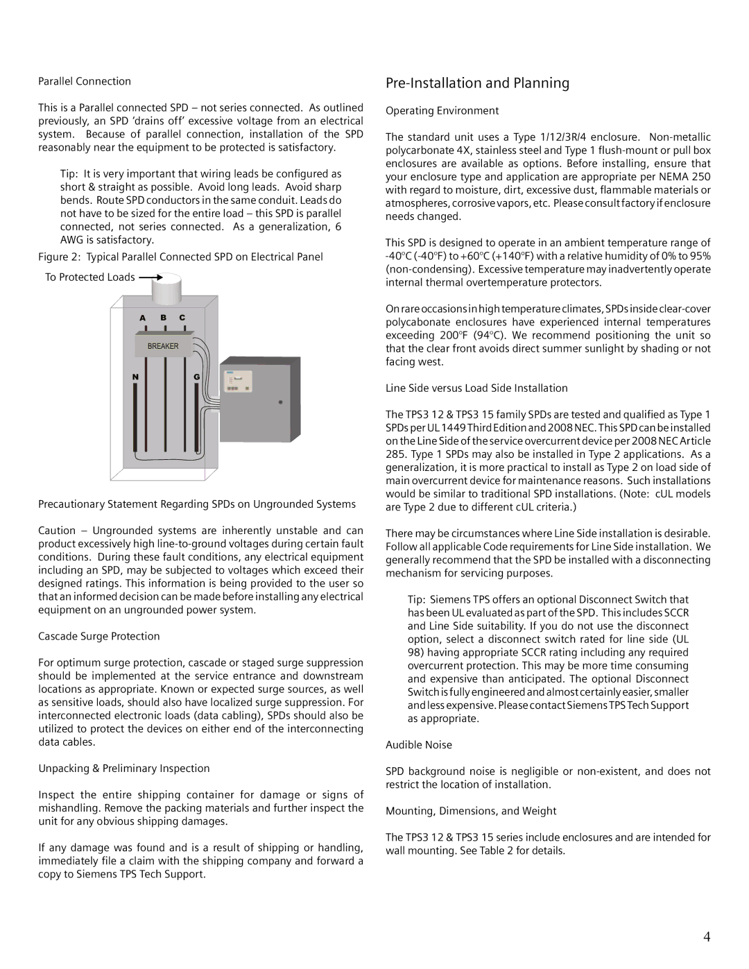
Figure 2: Typical Parallel Connected SPD on Electrical Panel
To Protected Loads 


A B C
BREAKER
N | G |
Precautionary Statement Regarding SPDs on Ungrounded Systems
Caution – Ungrounded systems are inherently unstable and can product excessively high
Cascade Surge Protection
For optimum surge protection, cascade or staged surge suppression should be implemented at the service entrance and downstream locations as appropriate. Known or expected surge sources, as well as sensitive loads, should also have localized surge suppression. For interconnected electronic loads (data cabling), SPDs should also be utilized to protect the devices on either end of the interconnecting data cables.
Unpacking & Preliminary Inspection
Inspect the entire shipping container for damage or signs of mishandling. Remove the packing materials and further inspect the unit for any obvious shipping damages.
If any damage was found and is a result of shipping or handling, immediately file a claim with the shipping company and forward a copy to Siemens TPS Tech Support.
Pre-Installation and Planning
Operating Environment
The standard unit uses a Type 1/12/3R/4 enclosure.
This SPD is designed to operate in an ambient temperature range of
On rare occasions in high temperature climates, SPDs inside
Line Side versus Load Side Installation
The TPS3 12 & TPS3 15 family SPDs are tested and qualified as Type 1 SPDs per UL 1449 Third Edition and 2008 NEC. This SPD can be installed on the Line Side of the service overcurrent device per 2008 NEC Article
285.Type 1 SPDs may also be installed in Type 2 applications. As a generalization, it is more practical to install as Type 2 on load side of main overcurrent device for maintenance reasons. Such installations would be similar to traditional SPD installations. (Note: cUL models are Type 2 due to different cUL criteria.)
There may be circumstances where Line Side installation is desirable. Follow all applicable Code requirements for Line Side installation. We generally recommend that the SPD be installed with a disconnecting mechanism for servicing purposes.
Tip: Siemens TPS offers an optional Disconnect Switch that has been UL evaluated as part of the SPD. This includes SCCR and Line Side suitability. If you do not use the disconnect option, select a disconnect switch rated for line side (UL
98)having appropriate SCCR rating including any required overcurrent protection. This may be more time consuming and expensive than anticipated. The optional Disconnect Switch is fully engineered and almost certainly easier, smaller and less expensive. Please contact Siemens TPS Tech Support as appropriate.
Audible Noise
SPD background noise is negligible or
Mounting, Dimensions, and Weight
The TPS3 12 & TPS3 15 series include enclosures and are intended for wall mounting. See Table 2 for details.
4