Terminals | Figure 3: NEMA 3R Drain Holes |
Terminals will accept 14 - 2 AWG conductor and are provided for line (phase), neutral (if used), and equipment safety ground connections. 8 AWG is the minimum recommended wire size because UL testing and evaluation was performed using 8 AWG.
Wire Size and Installation Torque
This is a
If other wire sizes are used, all conductors must be the same gauge. Note that larger conductor might appear to be beneficial. However, large conductor tends to have the same inductance as smaller conductor, thus netting limited improvement in exchange for being more difficult to work with.
Terminals accept 14 - 2 AWG conductor with 6 AWG being preferred. Coordinate conductor size and overcurrent protection per applicable codes.
If equipped, Disconnect Switch will accept 6 AWG to 1/0 AWG, with 6 AWG preferred. Torque connections to 18
System Grounding
An equipment grounding conductor must be used on all electrical circuits connected to the SPD.
For the best performance, use a single point ground system where the service entrance grounding electrode system is connected to and bonded to building steel, metallic piping, driven rods, etc. (NEC and IEEE Std
For sensitive electronics and computer systems, ground impedance should be as low as possible. When metallic raceway is used as an additional grounding conductor, an insulated grounding conductor should be run inside the raceway and sized per the NEC. Adequate electrical continuity must be maintained at all raceway connections. Do not use isolating bushings to interrupt a metallic raceway run.
A separate isolated ground for the SPD may isolate the SPD from the rest of the electrical system, thus decreasing performance. Ensure grounding system meets NEC. Proper equipment connections to grounding system and ground grid continuity should be verified via inspections and tested on a regular basis as part of a comprehensive electrical maintenance program.
On
NEMA 3R Drain Holes for Standard Steel Enclosure
In order to maintain a UL 3R rating, two 0.25” (6mm) holes must be drilled in opposite corners of the bottom surface of the enclosure. Take care to not damage internal SPD components. Remove any drilling remnants. (Do not perform on other enclosures or ratings.)
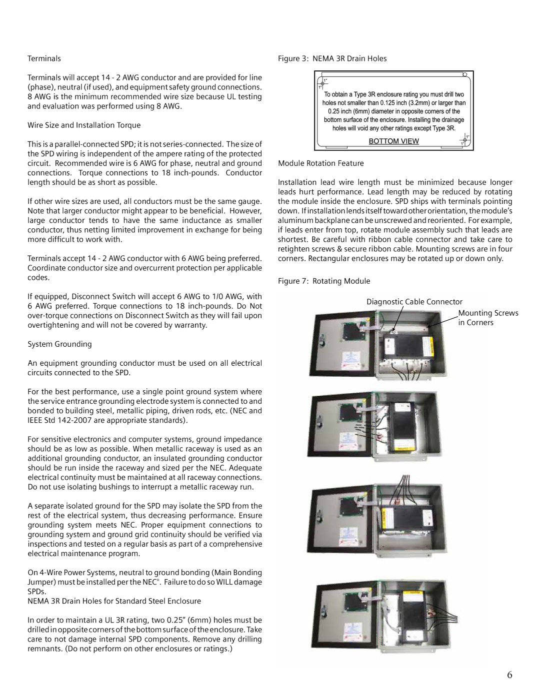
Module Rotation Feature
Installation lead wire length must be minimized because longer leads hurt performance. Lead length may be reduced by rotating the module inside the enclosure. SPD ships with terminals pointing down. If installation lends itself toward other orientation, the module’s aluminum backplane can be unscrewed and reoriented. For example, if leads enter from top, rotate module assembly such that leads are shortest. Be careful with ribbon cable connector and take care to retighten screws & secure ribbon cable. Mounting screws are in four corners. Rectangular enclosures may be rotated up or down only.
Figure 7: Rotating Module
Diagnostic Cable Connector
Mounting Screws
 in Corners
6