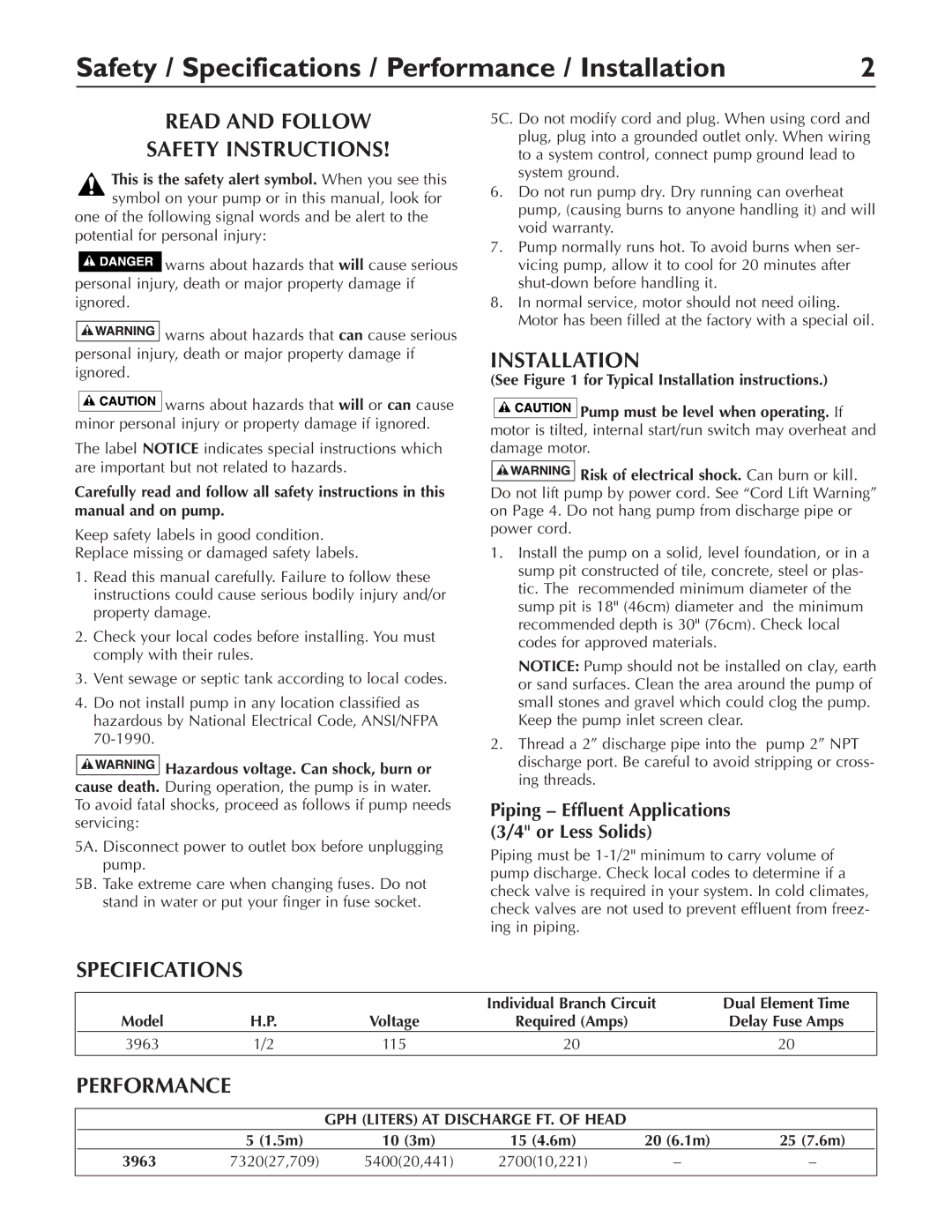
3963 specifications
Simer Pumps has established a reputation for reliability and innovation, and the Simer Pumps 3963 model exemplifies this commitment. Designed for versatility and efficiency, the 3963 model serves both residential and commercial applications, providing users with a powerful solution for various pumping needs.One of the standout features of the Simer Pumps 3963 is its robust motor. The pump is equipped with a heavy-duty electric motor that ensures durability and longevity. This high-performance motor delivers a superior flow rate, making it suitable for tasks ranging from draining pools to managing groundwater. It operates quietly, which adds to the overall comfort of its application in both residential and commercial environments.
The 3963 model employs advanced technology, including a thermoplastic construction that enhances resistance to corrosion and wear. This material choice makes the pump ideal for handling various fluids, including clean water, wastewater, and light chemicals. Additionally, the model boasts an engineered design that minimizes energy consumption while maximizing output, ensuring that users can benefit from its efficiency without incurring excessive operating costs.
A significant characteristic of the Simer Pumps 3963 is its automatic on/off switch, which provides a hands-free experience. This feature includes a built-in float switch that detects water levels and triggers the pump when necessary, ensuring that the area remains dry without user intervention. This technology is particularly beneficial for sump applications, where the risk of flooding is present.
The model also features easy installation processes, allowing users to set it up with minimal hassle. The pump is designed with standard connections that fit various piping systems, ensuring compatibility and ease of integration. Furthermore, maintenance is straightforward; the pump’s accessible design allows for quick troubleshooting and service, minimizing downtime.
In summary, the Simer Pumps 3963 is an exemplary model that combines innovative technology with robust design to meet the diverse needs of its users. Its powerful motor, durable materials, energy-efficient operation, and user-friendly features make it a reliable choice for those seeking a dependable pumping solution. Whether for residential use or in commercial settings, the Simer Pumps 3963 stands out as a top-tier option in the market.

