Initial Turbo Installation
Install Deflector
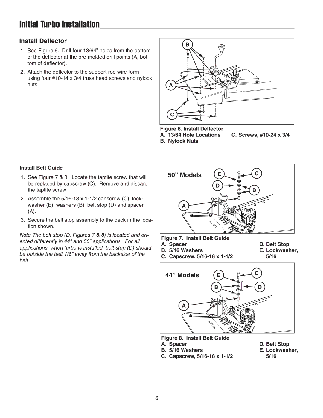
1.See Figure 6. Drill four 13/64” holes from the bottom of the deflector at the
2.Attach the deflector to the support rod
B |
A |
C |
Figure 6. Install Deflector
A. 13/64 Hole Locations C. Screws, #10-24 x 3/4 B. Nylock Nuts
Install Belt Guide
1.See Figure 7 & 8. Locate the taptite screw that will be replaced by capscrew (C). Remove and discard the taptite screw
2.Assemble the
(A).
3.Secure the belt stop assembly to the deck in the loca- tion shown.
Note The belt stop (D, Figures 7 & 8) is located and ori- ented differently in 44” and 50” applications. For all applications, when turbo is installed, belt stop (D) should be outside the belt 1/8” away from the backside of the belt.
50” Models | E | C |
D
B
A
Figure 7. Install Belt Guide |
| |
A. Spacer |
| D. Belt Stop |
B. 5/16 Washers |
| E. Lockwasher, |
C. Capscrew, | 5/16 | |
44” Models | E | C |
B ![]()
![]() D
D
A
Figure 8. Install Belt Guide |
|
A. Spacer | D. Belt Stop |
B. 5/16 Washers | E. Lockwasher, |
C. Capscrew, | 5/16 |
6
