Assembly
Attaching the Blade
To prevent personal injury, ! WARNING always disconnect plug from
power source before assembling parts, making adjustments, or changing blades.
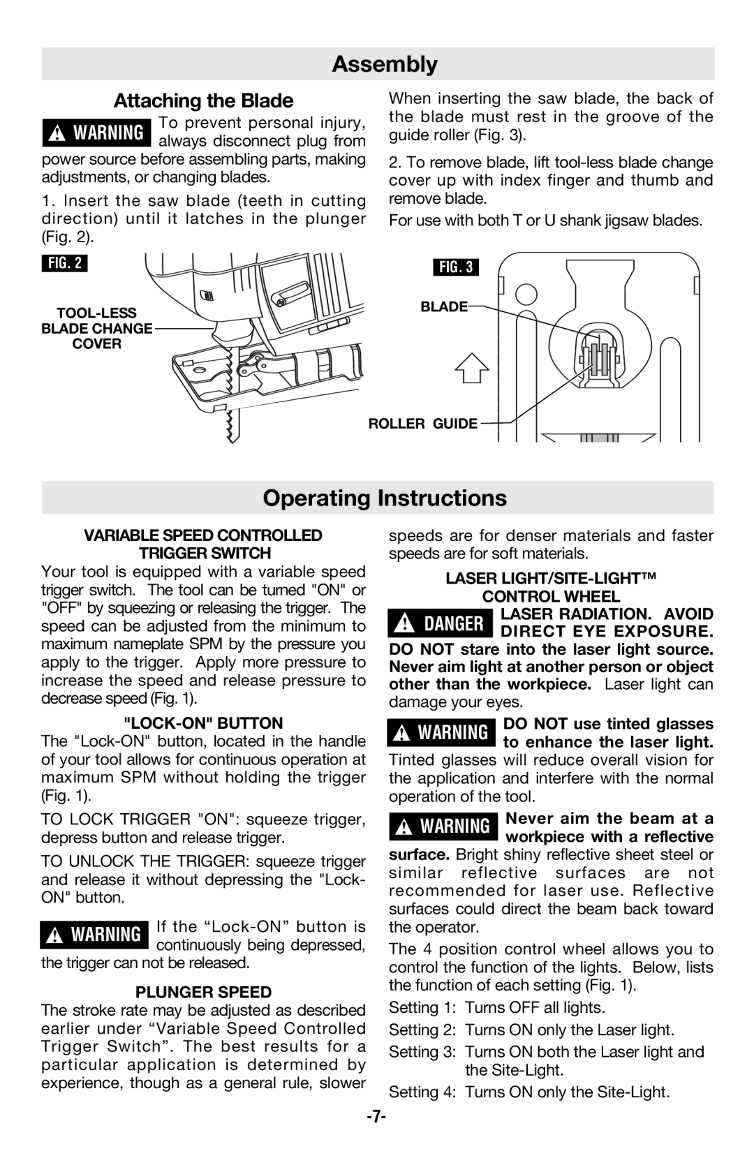
1. Insert the saw blade (teeth in cutting direction) until it latches in the plunger (Fig. 2).
When inserting the saw blade, the back of the blade must rest in the groove of the guide roller (Fig. 3).
2.To remove blade, lift
For use with both T or U shank jigsaw blades.
FIG. 2 | FIG. 3 |
BLADE | |
| |
BLADE CHANGE |
|
COVER |
|
| ROLLER GUIDE |
Operating Instructions
VARIABLE SPEED CONTROLLED
TRIGGER SWITCH
Your tool is equipped with a variable speed trigger switch. The tool can be turned "ON" or "OFF" by squeezing or releasing the trigger. The speed can be adjusted from the minimum to maximum nameplate SPM by the pressure you apply to the trigger. Apply more pressure to increase the speed and release pressure to decrease speed (Fig. 1).
"LOCK-ON" BUTTON
The
TO LOCK TRIGGER "ON": squeeze trigger, depress button and release trigger.
TO UNLOCK THE TRIGGER: squeeze trigger and release it without depressing the "Lock- ON" button.
!WARNING If the
the trigger can not be released.
PLUNGER SPEED
The stroke rate may be adjusted as described earlier under “Variable Speed Controlled Trigger Switch”. The best results for a particular application is determined by experience, though as a general rule, slower
speeds are for denser materials and faster speeds are for soft materials.
LASER
CONTROL WHEEL
!LASER RADIATION. AVOID DANGER DIRECT EYE EXPOSURE.
DO NOT stare into the laser light source. Never aim light at another person or object other than the workpiece. Laser light can
damage your eyes.
!WARNING DO NOT use tinted glasses to enhance the laser light.
Tinted glasses will reduce overall vision for the application and interfere with the normal operation of the tool.
!WARNING Never aim the beam at a workpiece with a reflective
surface. Bright shiny reflective sheet steel or similar reflective surfaces are not recommended for laser use. Reflective surfaces could direct the beam back toward the operator.
The 4 position control wheel allows you to control the function of the lights. Below, lists the function of each setting (Fig. 1).
Setting 1: Turns OFF all lights.
Setting 2: Turns ON only the Laser light.
Setting 3: Turns ON both the Laser light and the
Setting 4: Turns ON only the
