Safety Information

Section 1 - Setting up the Wall Switch Receiver

Section 2 - Setting up the Wireless Wall Switch Transmitter

INSTALLATION INSTRUCTIONS

WIRELESS 3 WAY ON/OFF/DIMMER KIT

Model: SK7

Turn o￿ power to the circuit breaker before installing.

If you are uncertain or uncomfortable performing this installation, please consult a quali￿ed electrician. This manual should also be kept for future reference.

For indoor use only.

DO NOT use this product to control loads over the speci￿ed maximum rating. For dimming function, the light bulbs must be dimmable.

The device is approved by the FCC and it complies with Part 15 of the FCC Rules. Its operation is subject to the following two conditions:

1.This device may not cause harmful interference.

2.This device must accept any interference that may cause undesired operation.

WARNING: Turn o￿ power to the circuit that you plan on installing the Wall Switch to, at the circuit breaker. Failure to turn o￿ power at the circuit breaker can result in electrical shock, causing severe or fatal injury.

NOTE: The Wall Switch is designed to operate incandescent light or dimmable compact ￿uorescent light with a maximum load of 300W at 120VAC. Light bulbs must be dimmable in order to achieve dimming function.

NOTE: If you already have an existing 3 Way Switch, disable one switch and replace the other switch with the Wall Switch Receiver.

4.Make sure the air gap switch is in the o￿ position and then turn the circuit back on.

5.Place the air gap switch to on position. The two blue LEDs will be on. If the blue LEDs remain o￿, please check and ensure the light bulb is installed and in good position and that the wires are connected correctly.

6.After the Wall Switch is installed, tap the metal touch plate to turn the lights on and o￿.

INSTALLING WITH DOUBLE SIDED TAPE

NOTE: The Wireless Wall Switch Transmitter comes with a lithium battery already installed. Remove the battery isolator tag from the Wireless Wall Switch transmitter before installing.

1.

First clean the wall surface where you plan to install the Wireless Wall Switch


transmitter.

2.

Place the two foam tapes (E) on the back of the Wireless Wall Switch transmitter


plate.

3.


WARNING: Changes or modi￿cations to this unit not expressly approved by the party responsible of compliance could void the user’s atuhority to operate the equipment.

Technical Speci￿cations

Input Voltage

120V AC, 60Hz


Standby Current

0.2mA


Minimum Load

10W


Maximum Load

300W at 120VAC


Operating Frequency

318MHz


Operational Temperature

-4°F - 140°F (-20°C - 60°C)


Humidity

5% - 95%


Range

Up to 500 feet in open area

1.Loosen the screws on the wallplate cover of the Wall Switch receiver and remove it before installing.

2.Install the Wall Switch with the 3 wires, Live, Load and Ground. Use the provided wire nuts (C) to connect these wires respectively to the existing wires from the wall. Neutral wire is not required and cannot be connected to the Wall Switch Receiver.

3.After all the wires are connected, ensure that all of the wire connectors are attached securely and there should be no exposed copper wiring. Secure the Wall Switch with screws.

Ground

GreenLoad

Red

Live

Black

Blue LEDs

ON Position

OFF Position

Air Gap

Switch

Touch Plate

Peel o￿ the foam tape cover and stick it to the wall surface.

Place double-sided foam tape

Congratulations on your purchase of the SkylinkHomeTM Wireless 3 Way On/O￿/ Dimmer Kit, model SK7. Simply replace your existing wall switch with the Skylink Wall Switch receiver and mount the Wireless Wall Switch Transmitter anywhere you would like to control your lighting.

Grey Antenna

NOTE: Do not cut the antenna.

Warranty

Package Contents

Section 2 - Setting up (continued)

Section 3 - Operation

ONE YEAR WARRANTY

This product is guaranteed to be free of defects in materials and workmanship for

1 year from the date of purchase. If this product is defective, call 1-800-304-1187 for repair or replacement parts. Guarantee does not include normal wear and tear or batteries.

If you have any questions, problems or missing parts, please call Skylink Customer Support: 9:00am - 5:00pm EST, Monday-Friday.

AB

CD

INSTALLING WITH SCREWS

NOTE: The Wall Mount transmitter comes with a lithium battery already installed. Remove the battery isolator tag from the Wall Mount Transmitter before installing.

Installing to an Existing Wall Switch

1.Loosen the screws on the wallplate cover of the Wireless Wall Switch transmitter and tighten the two included screws (D) on the back plate to the existing wall box.

2.Tighten the two screws on the wallplate to the back plate to secure it.

3.The Wireless Wall Switch transmitter is now ready to be controlled.

D

Wall Switch Receiver

NOTE: Make sure the Air Gap Switch is in the on position before you start.

1.To turn the light on and o￿, tap the Wall Switch metal touch plate..

Tap the touch plate (On/O￿)

Wireless Wall Switch Transmitter

1.To turn the light on and o￿, push the Wireless Wall Switch pad from one position to the other.

Push

Push

1-800-304-1187

Or e-mail us at support@skylinkhome.com

www.skylinkhome.com

CUSTOMER SERVICE

17 Sheard Avenue,

Brampton, Ontario,

Canada L6Y1J3

P/N : 101Y156 Rev:0 ©2014 SKYLINK GROUP.

E

Part

Description

Quantity


A

Wall Switch Receiver

1


B

Wireless Wall Switch Transmitter

1


C

Wire Nuts

3


D

Screws and anchors

2


E

Double-sided Foam Tape

2


Existing Wall Box (No Anchor)

Installing on New Wall Surface

1.Drill two small pilot holes based on the two mounting screw positions and insert the anchors (D) before tightening the back plate with screws (D).

2.Tighten the two screws on the wall plate to the back plate to secure it.

3.The Wireless Wall Switch transmitter is now ready to be controlled.

DD

2. To dim or brighten the lights, push the Wireless Wall Switch pad to turn on the lights then press and hold the same (upper) pad to dim or brighten the lights.

2.To dim or brighten the lights, tap the metal touch plate to turn on the lights then press and hold to dim or brighten the lights.

Press and hold

Press and hold the

touch plate (Dimming)

Drill 2 pilot holes & insert anchors

Page 1
Image 1
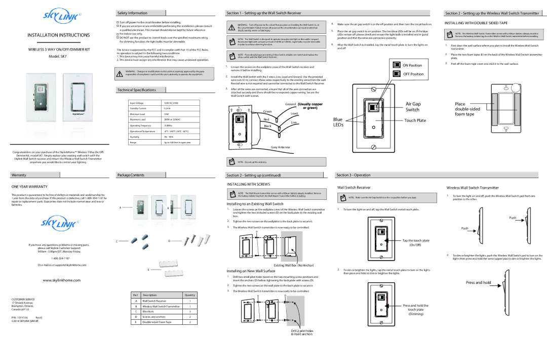
SkyLink SK7 installation instructions Wireless 3 WAY ON/OFF/DIMMER KIT, Installing with Double Sided Tape

SK7 specifications

SkyLink SK7 is a cutting-edge satellite communication system designed to provide seamless connectivity for a variety of applications, ranging from government to commercial uses. With a focus on reliability, speed, and coverage, the SK7 is a game-changer in the satellite communication landscape.

One of the standout features of the SkyLink SK7 is its advanced phased array antenna technology. This innovative design allows for faster signal acquisition and tracking, enabling users to maintain a stable connection even in challenging environments. This is particularly beneficial for mobile applications, such as maritime and aviation sectors, where connectivity can often be intermittent.

Another significant characteristic of the SK7 is its high throughput capability. The system supports multi-gigabit data rates, making it suitable for bandwidth-intensive applications, such as high-definition video streaming and large data transfers. This ensures that organizations can rely on the SK7 for their critical communication needs, without compromising on speed or efficiency.

The SkyLink SK7 also incorporates powerful encryption protocols, ensuring that data transmitted over the network is secure and protected from unauthorized access. This is especially crucial in industries where sensitive data is transmitted, such as defense and finance. The system is designed to meet stringent compliance standards, giving users peace of mind when it comes to data security.

In terms of user experience, the SK7 offers an intuitive interface for easy operation and management. Users can monitor their connection status, manage bandwidth, and troubleshoot issues quickly and efficiently. This user-friendly approach reduces the need for extensive training and allows for smoother implementation across various organizations.

Moreover, the SK7 is built to be highly resilient, with robust hardware capable of withstanding harsh environmental conditions. This durability makes it an ideal choice for remote locations and extreme weather scenarios, ensuring constant connectivity when users need it the most.

Additionally, the SkyLink SK7 is compatible with various satellite constellations, allowing for flexible deployment options. Users can choose between different service providers and configurations, tailoring the system to their specific needs and objectives.

In conclusion, the SkyLink SK7 is a state-of-the-art satellite communication system that combines advanced technologies with robust features to deliver exceptional performance. Its high throughput, security measures, user-friendly interface, and resilience make it an ideal solution for organizations requiring reliable connectivity in an increasingly connected world.