Description of Hardware 1
Each of these ports support
SFP Slots
The Small Form Factor Pluggable (SFP) transceiver slots are shared with two of the
Port and System Status LEDs
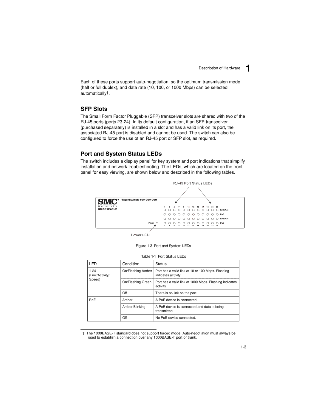
The switch includes a display panel for key system and port indications that simplify installation and network troubleshooting. The LEDs, which are located on the front panel for easy viewing, are shown below and described in the following tables.
Power LED
Figure 1-3 Port and System LEDs
Table 1-1 Port Status LEDs
LED | Condition | Status | |
|
|
| |
On/Flashing Amber | Port has a valid link at 10 or 100 Mbps. Flashing | ||
(Link/Activity/ |
| indicates activity. | |
Speed) |
|
| |
On/Flashing Green | Port has a valid link at 1000 Mbps. Flashing indicates | ||
| |||
|
| activity. | |
|
|
| |
| Off | There is no link on the port. | |
|
|
| |
PoE | Amber | A PoE device is connected. | |
|
|
| |
| Amber Blinking | A PoE device is connected and data is being | |
|
| transmitted. | |
| Off | No PoE device connected. | |
|
|
|
†The