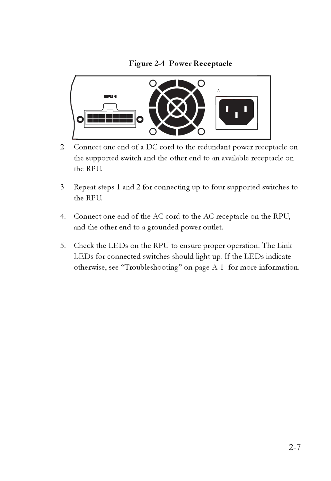
Figure 2-4 Power Receptacle
2.Connect one end of a DC cord to the redundant power receptacle on the supported switch and the other end to an available receptacle on the RPU.
3.Repeat steps 1 and 2 for connecting up to four supported switches to the RPU.
4.Connect one end of the AC cord to the AC receptacle on the RPU, and the other end to a grounded power outlet.
5.Check the LEDs on the RPU to ensure proper operation. The Link LEDs for connected switches should light up. If the LEDs indicate otherwise, see “Troubleshooting” on page