•
•The RPU will operate under a
Front and Rear Panels
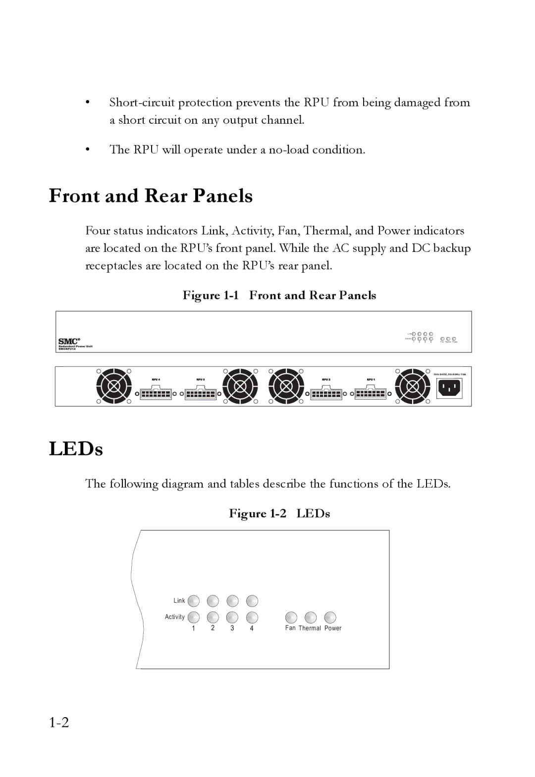
Four status indicators Link, Activity, Fan, Thermal, and Power indicators are located on the RPU’s front panel. While the AC supply and DC backup receptacles are located on the RPU’s rear panel.
Figure 1-1 Front and Rear Panels
Link ![]()
Activity ![]()
Fan Thermal Power
LEDs
The following diagram and tables describe the functions of the LEDs.
Figure 1-2 LEDs
Link ![]()
Activity
Fan Thermal Power