Operating the Tractor
A |
B |
Figure 6. Raising & Lowering Mower
A.Mower Height adjuster / Lift Lever
B.Hopper Lever
B |
C |
A |
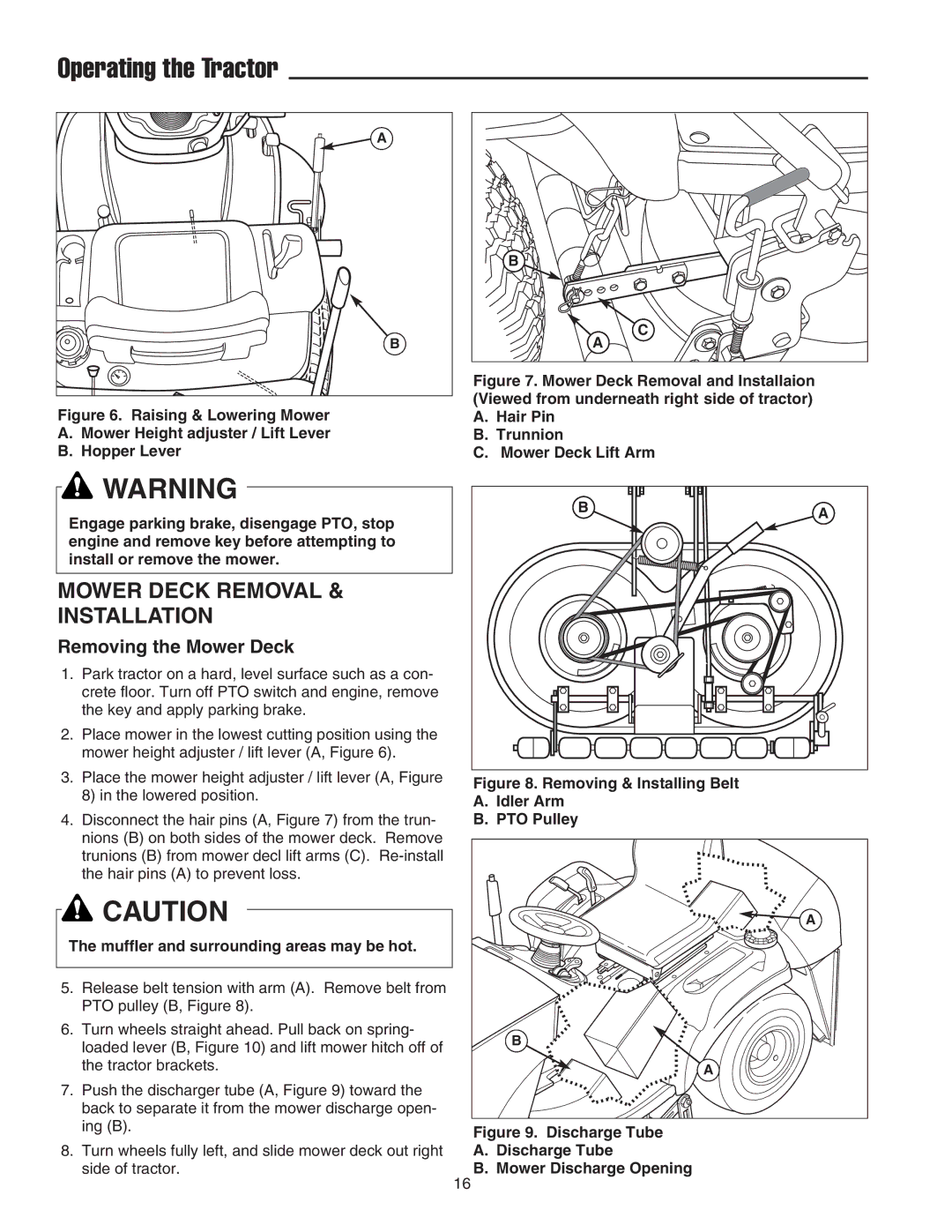
Figure 7. Mower Deck Removal and Installaion (Viewed from underneath right side of tractor)
A.Hair Pin
B.Trunnion
C.Mower Deck Lift Arm
![]() WARNING
WARNING
Engage parking brake, disengage PTO, stop engine and remove key before attempting to install or remove the mower.
MOWER DECK REMOVAL &
INSTALLATION
Removing the Mower Deck
1.Park tractor on a hard, level surface such as a con- crete floor. Turn off PTO switch and engine, remove the key and apply parking brake.
2.Place mower in the lowest cutting position using the mower height adjuster / lift lever (A, Figure 6).
3.Place the mower height adjuster / lift lever (A, Figure 8) in the lowered position.
4.Disconnect the hair pins (A, Figure 7) from the trun- nions (B) on both sides of the mower deck. Remove trunions (B) from mower decl lift arms (C).
![]() CAUTION
CAUTION
The muffler and surrounding areas may be hot.
5.Release belt tension with arm (A). Remove belt from PTO pulley (B, Figure 8).
6.Turn wheels straight ahead. Pull back on spring- loaded lever (B, Figure 10) and lift mower hitch off of the tractor brackets.
7.Push the discharger tube (A, Figure 9) toward the back to separate it from the mower discharge open- ing (B).
8.Turn wheels fully left, and slide mower deck out right side of tractor.
B | A |
|
Figure 8. Removing & Installing Belt
A.Idler Arm
B.PTO Pulley
A |
B |
A |
Figure 9. Discharge Tube
A.Discharge Tube
B.Mower Discharge Opening
16