![]() WARNING
WARNING
Make certain direction of travel is clear of objects, people and animals.
Always look DOWN AND BEHIND before backing!
OPERATING THE MOWER
1.When traveling to or from the work site, fully raise the mower using the mower lift lever (A, Figure 4). At the work site, lower mower using the lift lever.
2.Use the
3.Engage the parking brake. Make sure the PTO switch is disengaged.
4.Start the engine (see STARTING THE ENGINE).
5.Fully lower the mower using the attachment lift lever.
6.Set the throttle to FULL.
7.Engage the PTO (Mower Deck).
8.Begin mowing. See Section LC for tips on mowing patterns, lawn care, and troubleshooting information.
9.When finished, shut off the PTO and raise the mower using the attachment lift control lever.
10. Stop the engine (see STOPPING THE RIDER).
NOTE: Cutting height scale is located on the quadrant at base of lift lever. Scale is numbered 1 thru 4, with 4 rep- resenting the highest cutting height.
PUSHING THE RIDER BY HAND
1.Disengage the PTO and turn the engine off.
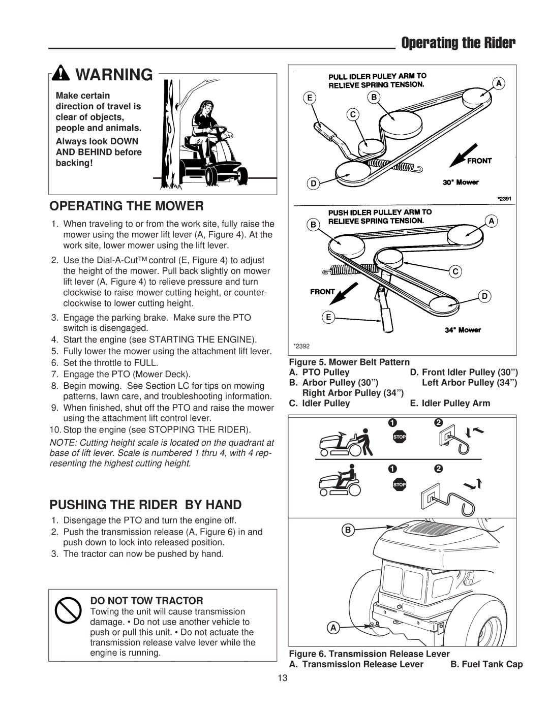
2.Push the transmission release (A, Figure 6) in and push down to lock into released position.
3.The tractor can now be pushed by hand.
DO NOT TOW TRACTOR
Towing the unit will cause transmission damage. • Do not use another vehicle to push or pull this unit. • Do not actuate the transmission release valve lever while the engine is running.
Operating the Rider
*2392
Figure 5. Mower Belt Pattern |
|
|
| |
A. PTO Pulley | D. Front Idler Pulley (30”) | |||
B. Arbor Pulley (30”) | Left Arbor Pulley (34”) | |||
Right Arbor Pulley (34”) |
|
|
| |
C. Idler Pulley | E. Idler Pulley Arm | |||
|
|
|
|
|
|
|
|
|
|
|
|
|
|
|
B
A
Figure 6. Transmission Release Lever |
|
A. Transmission Release Lever | B. Fuel Tank Cap |
13