Manuals
/
Snapper
/
Lawn and Garden
/
Lawn Mower Accessory
Snapper
6-3162, 7-3571
manual
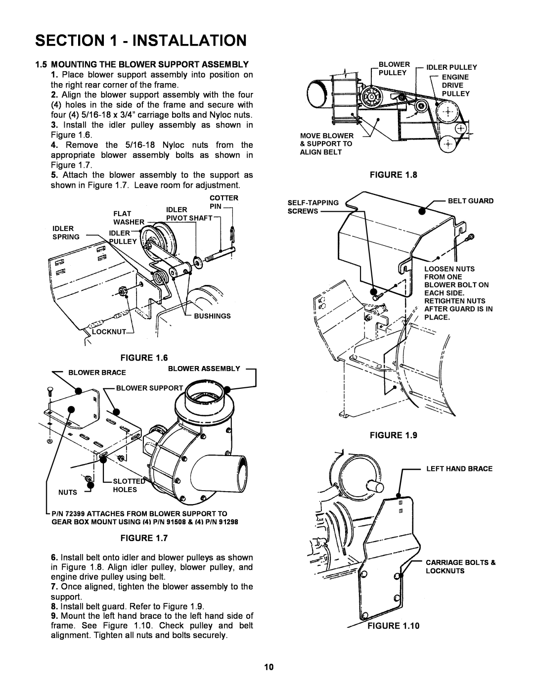
Installation, 1.5MOUNTING THE BLOWER SUPPORT ASSEMBLY
Models:
7-3571
6-3162
1
10
17
17
Download
17 pages
10.73 Kb
7
8
9
10
11
12
13
14
Install
Warranty
Maintenance
Blower Assembly
Safety
Page 10
Image 10
Page 9
Page 11
Page 10
Image 10
Page 9
Page 11
Contents
MANUAL No. 7-3571Rev. 1, 7/28/00
#6-3162BLOWER KIT for
COPYRIGHT SNAPPER INC ALL RIGHTS RESERVED
PROTECTION AGAINST TIPOVERS
IMPORTANT SAFETY INSTRUCTIONS
PROTECTION FOR CHILDREN
PREPARATION
MAINTENANCE
OPERATION
MAINTENANCE
NEW DECAL
DECALS
24773
WARRANTY
TABLE OF CONTENTS
INSTALLATION
SECTION
1.2DISCHARGE ADAPTER INSTALLATION
SECTION 1 - INSTALLATION
INTRODUCTION
SECTION 1 - INSTALLATION
FIGURE 1.5A
SECTION 1 - INSTALLATION
1.5MOUNTING THE BLOWER SUPPORT ASSEMBLY
PAGE NO
CONTENTS
SECTION 2 - PARTS IDENTIFICATION
Blower, Idler, Adapter & Blade Assemblies
BLOWER, IDLER, ADAPTER & BLADE ASSEMBLIES
B BLOWER KIT
PART NO. DESCRIPTION
BLOWER KIT
BLOWER ASSEMBLY
PART NO. DESCRIPTION
1 YEAR LIMITED WARRANTY
MANUAL No. 7-3571Rev. 1, 7/28/00
#6-3162BLOWER KIT for
COPYRIGHT SNAPPER INC ALL RIGHTS RESERVED
Top
Page
Image
Contents